"IN PROGRESS"
PAGE 2
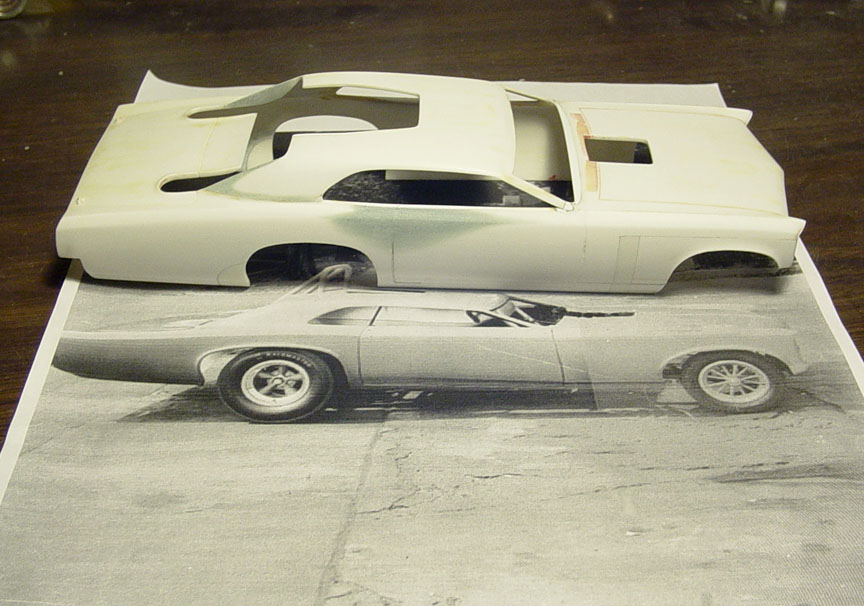
On these pages you'll see how we create our master models,
so you can see the labor of love that goes into all our products.
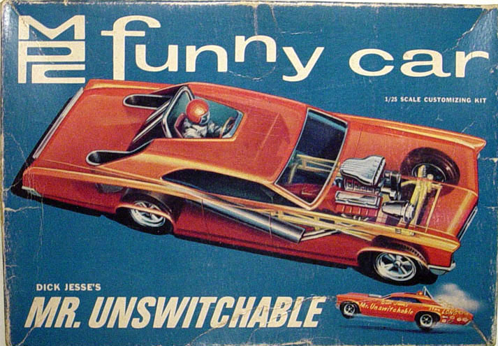
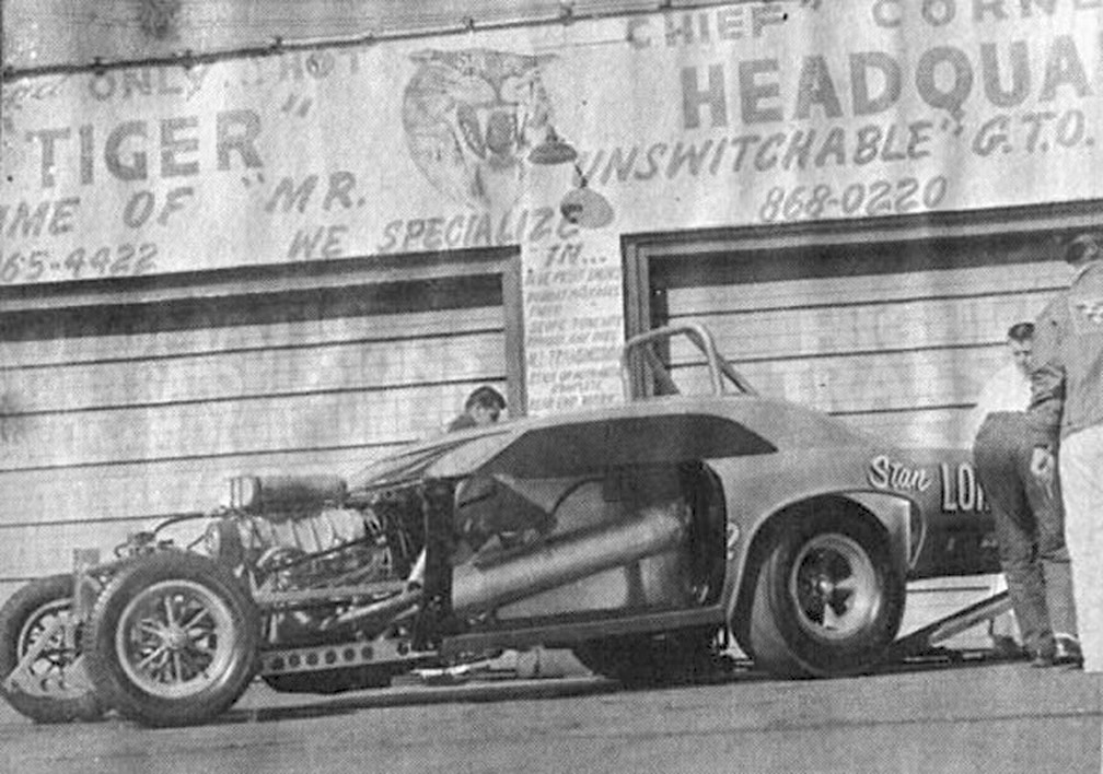
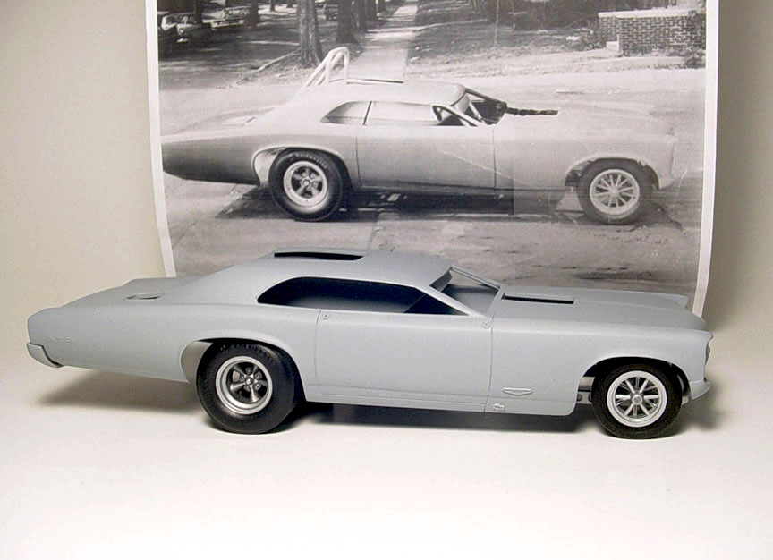
This is not going to be a re-cast of the incorrect mpc kit.
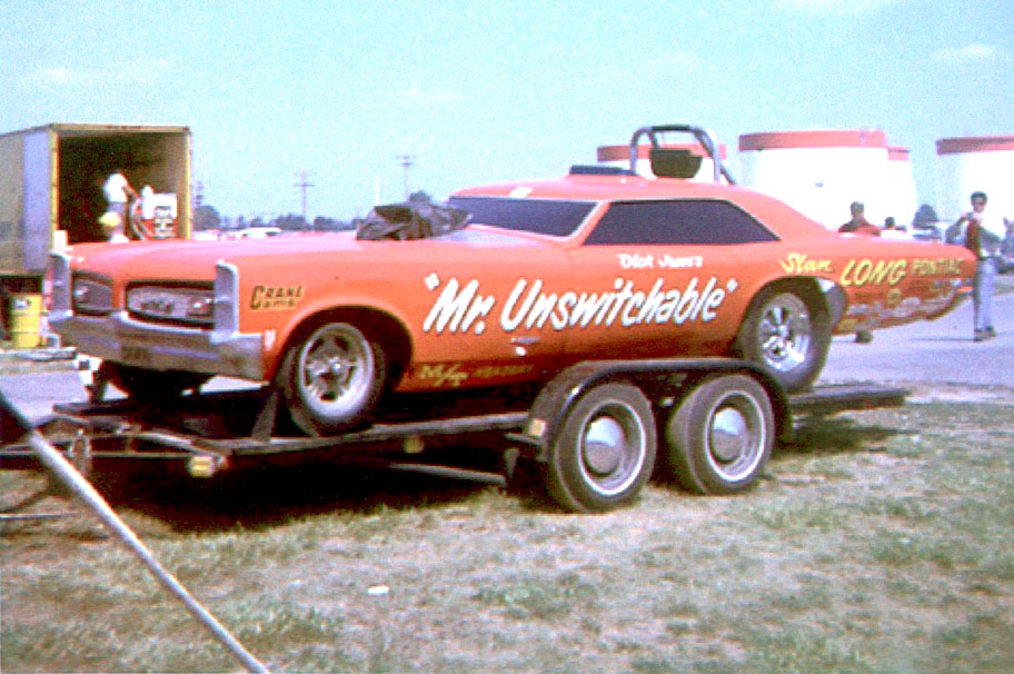
Our model will be designed to be an accurate replica of the original Mr. Unswitchable !
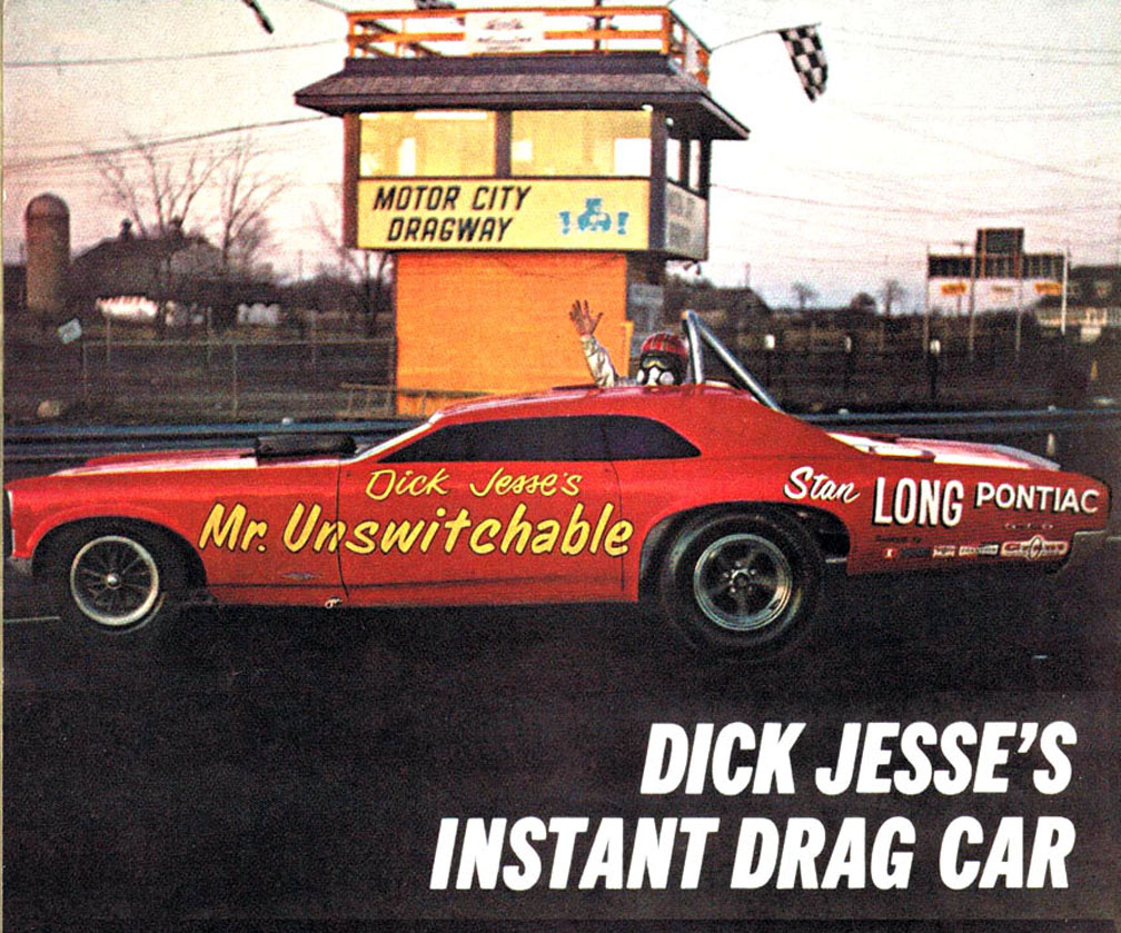
The magazine articles claim the Mr. Unswitchable is 2" shorter than a stock GTO and the wheel base is 120".
But after measuring a stock '67 GTO (which has a 115" wheel base), the math doesn't add up to having a 120" wheelbase.
Lets do the math....
1. The magazine article claims a stock '67 GTO wheel base is a 115"..... That is correct !
2. Jesse moved the rear axle forward 15"....... That looks to be correct !
3. Moved the front wheel wells forward 13" on one magazine and 20" on another magazine.....
13" would be correct, for the early un-stretched Mr. Unswitchable version that we are doing.
4. Article's make claim the Mr. Unswitchable is 2" shorter than a stock GTO.... Most likely due to fiberglass bumpers.
5. After doing the alterations, the correct wheel base distance would be: 113 Inches !
 It is possible the article made a mistake when they later did the stretched version (shown here),
which looks like 120" wheelbase.
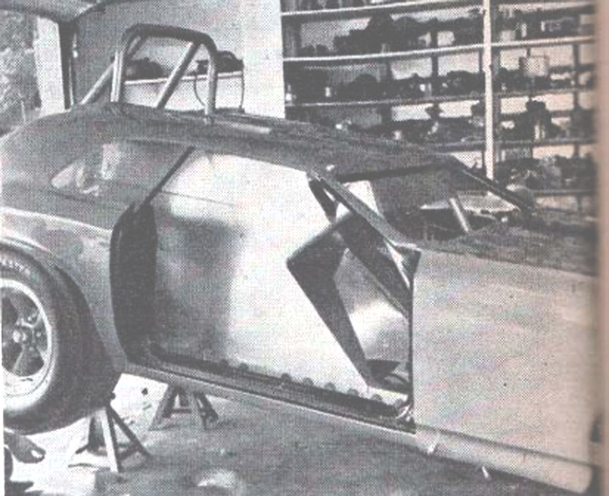
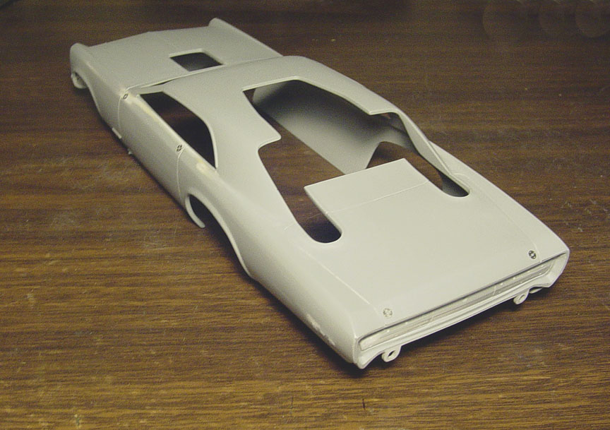
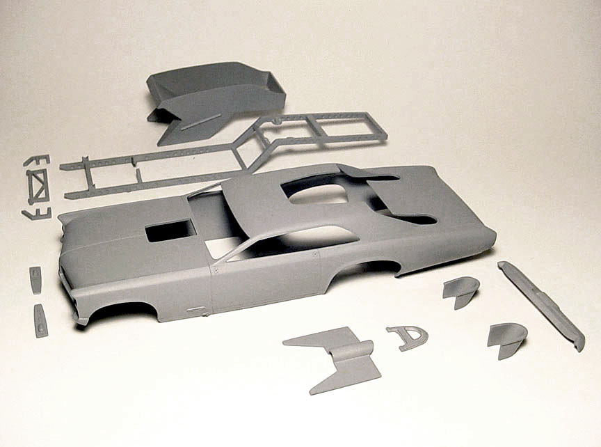
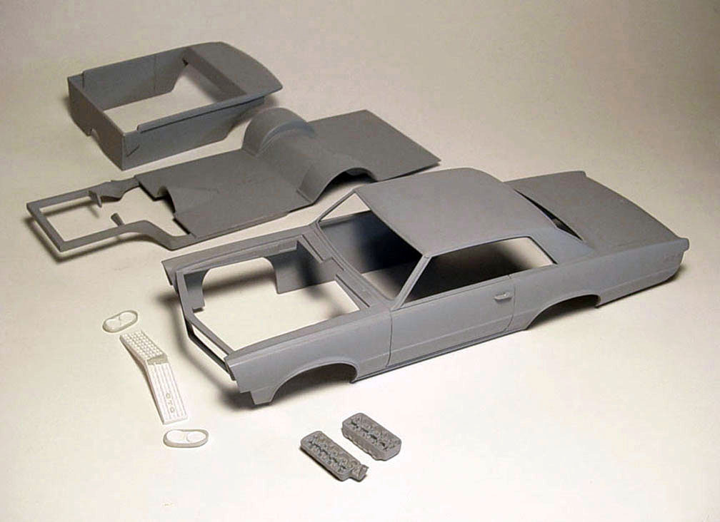
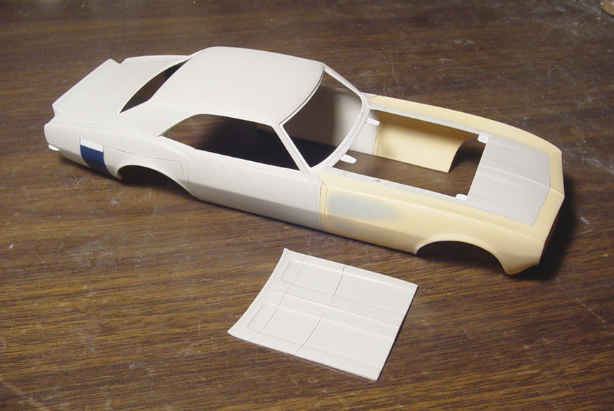
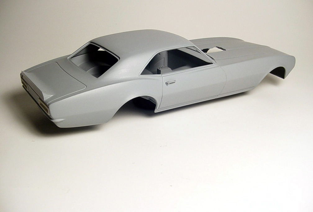
BODY WORK
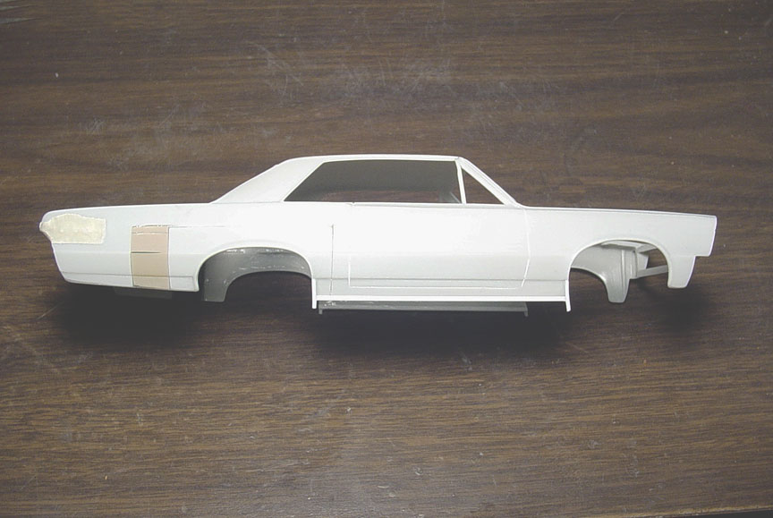
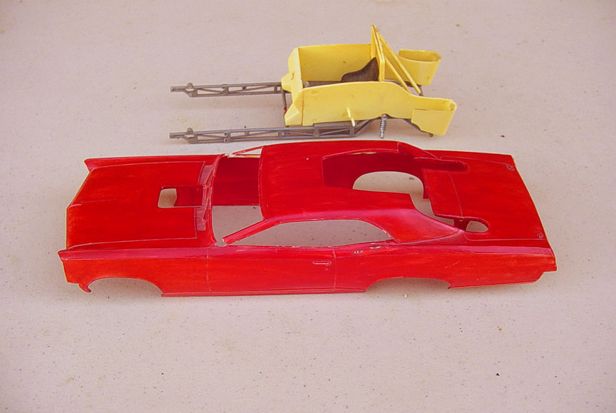 The MPC "MR. UNSWITCHABLE" FUNNY CAR model kit body is not an accurate replica
of the 1:1 car.... and it never had a Logghe Chassis !
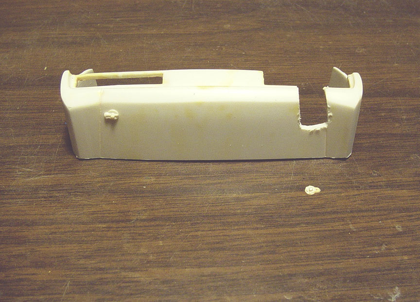
The only reason were starting with an original MPC Mr. Unswitchable body and not a re-issue '67 Pontiac GTO,
is that the exhaust holes are already in the trunk and should save some time ?.... otherwise I would have rather
started with a reissued MPC '67 PONTIAC GTO body.
 After stripping the paint, the body had some glue slop that needed to be removed around all the window
openings and then the entire body and roof was re-surfaced.
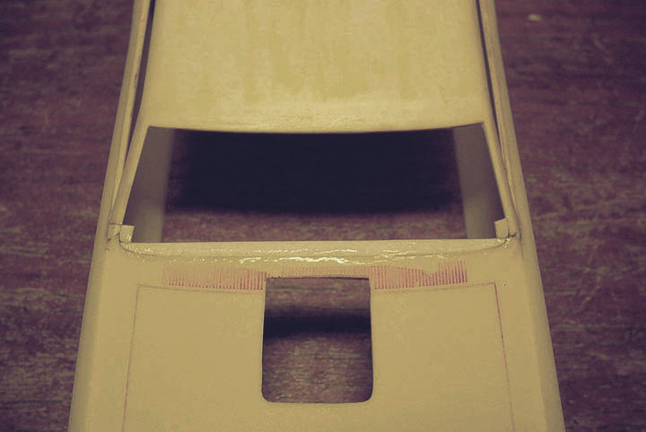
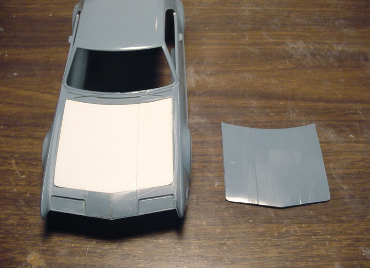
The wiper blades were removed and the cowl vents and hood lines were filled in with Super Glue.
 The interior of the body and roof was resurfaced and thinned, all but the glue stains.

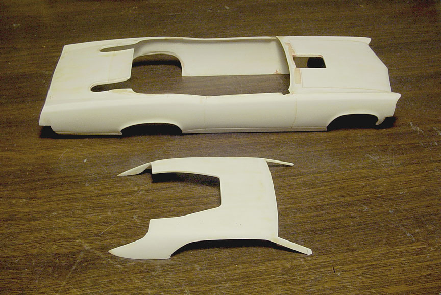
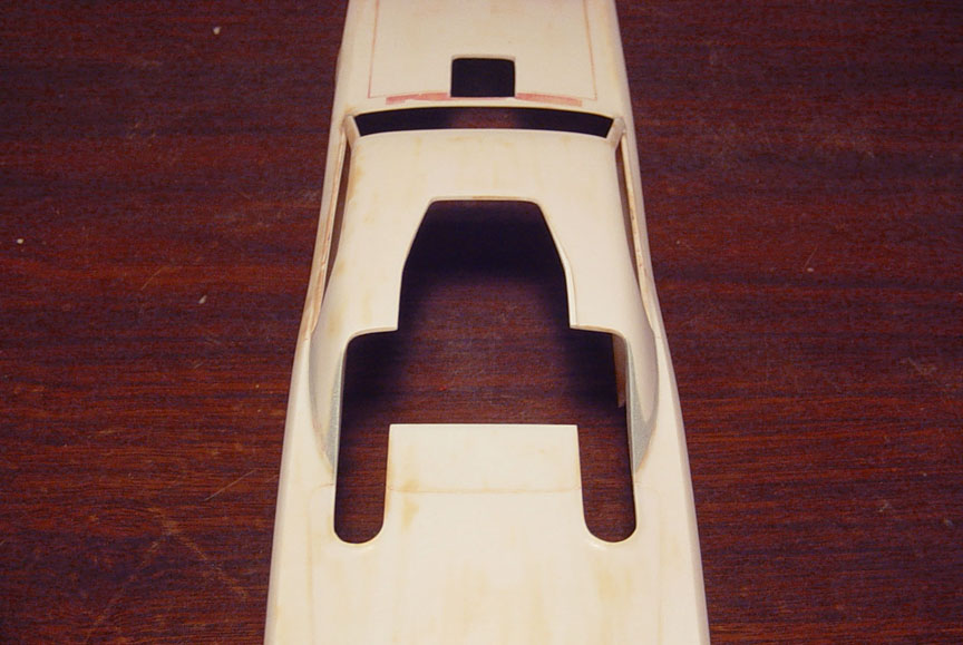
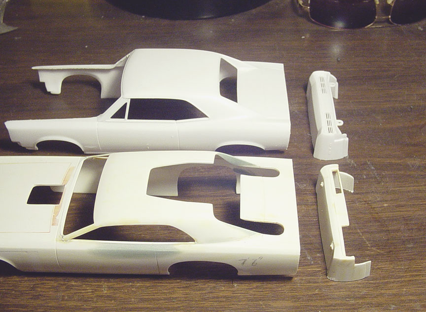
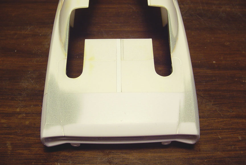
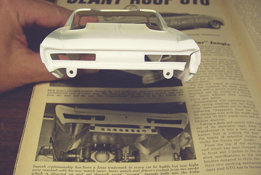
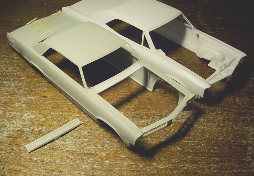
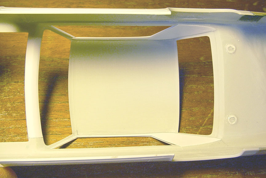
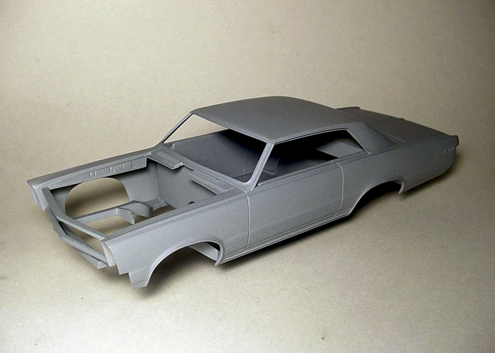
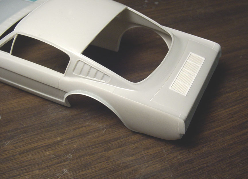
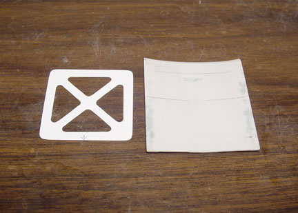
 After doing measurements on the stock mpc '67 GTO roof, it was determined that the
mpc Mr. Unswitchable sail panel was cut at the bottom and not the middle, like the real car was......
(See the cuts in the 2nd photo).
This means that the mpc sail panel is 3 inches too short at the bottom and will need to be lengthened 3" to give it a stock length.
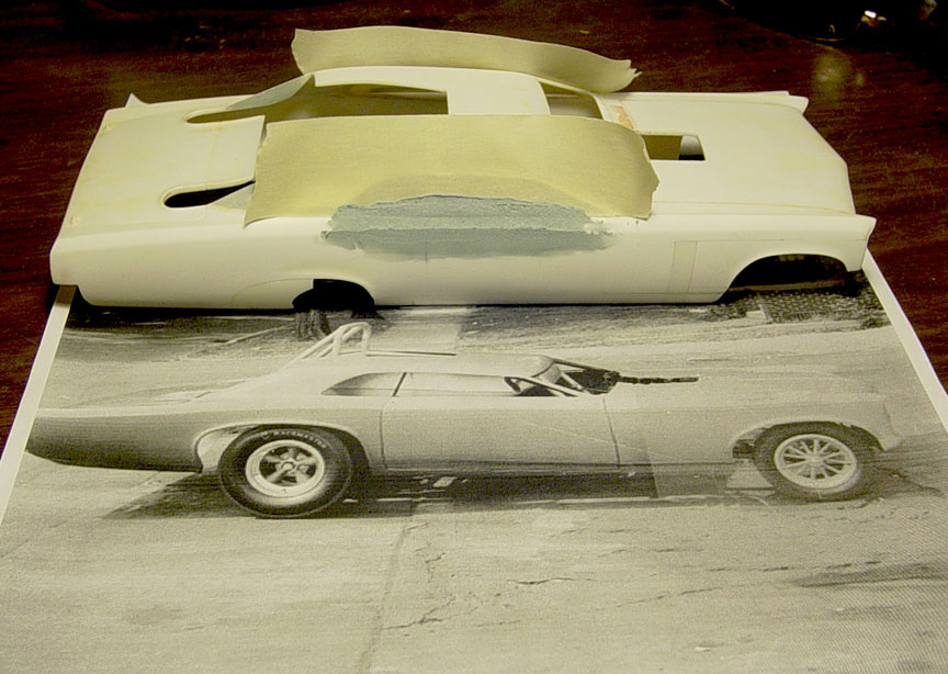
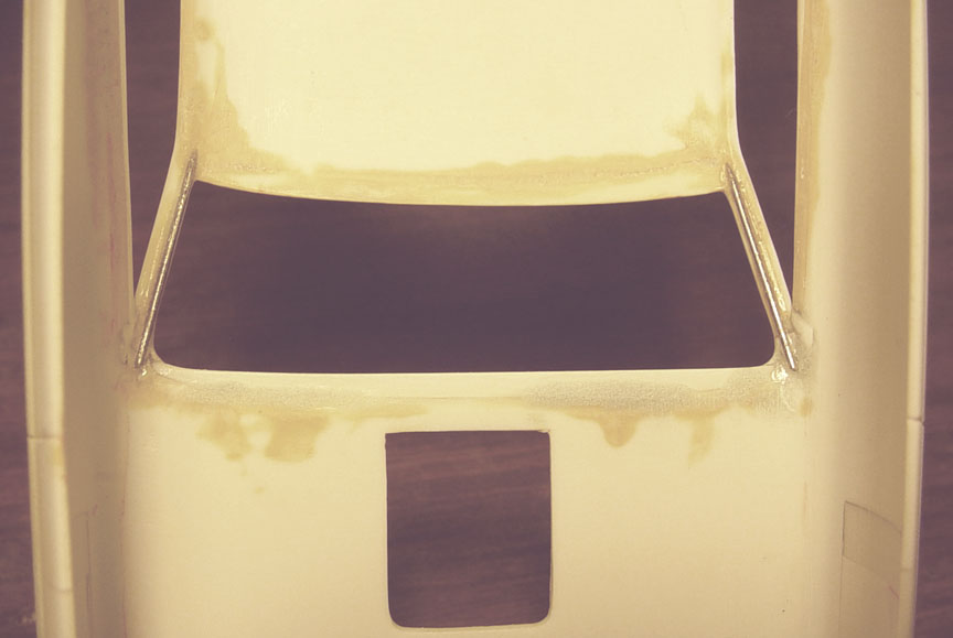
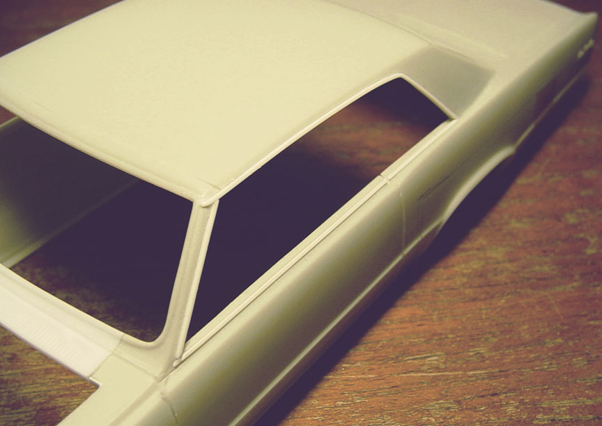
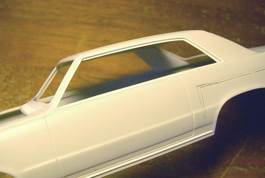
The article states that the roof was chopped 13 inches in the front and 7 inches in the rear to give it the rake,
so those measurements were made to scale on our body as well.
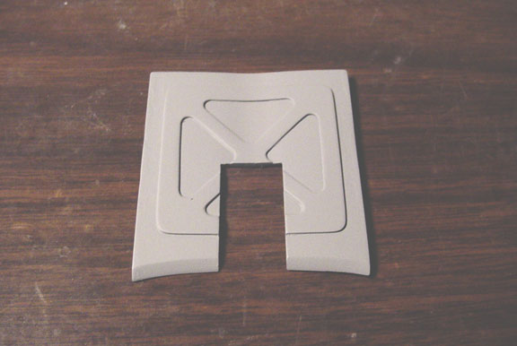
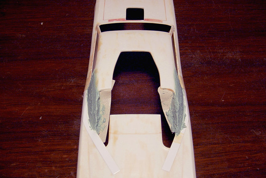 Evercoat Putty is added to lengthen and re-shape the sail panel.
 The roof opening for the driver was also mis-shaped, so a piece of .040 X .060" was used
to to match the other side. The inner walls of the sail panel were also straightened.
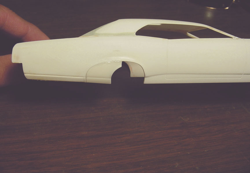
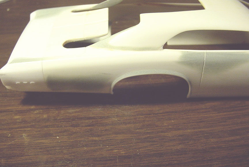
 In the magazine articles, they state that the front wheels were moved forward 13 inches.
After comparing to a stock '67 GTO, we see that the MPC Mr. Unswitchable model body had the wheels moved forward
only 8 inches..... Another 5" will need to be moved forward !
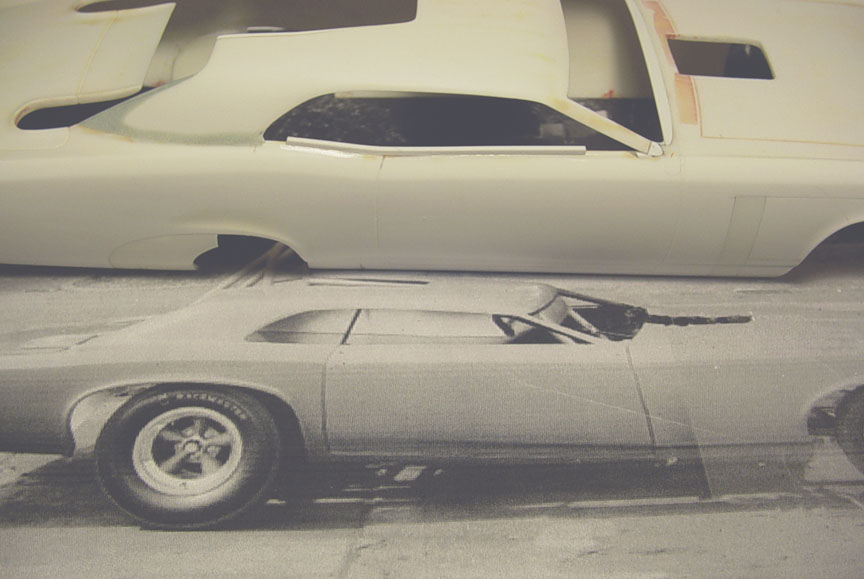
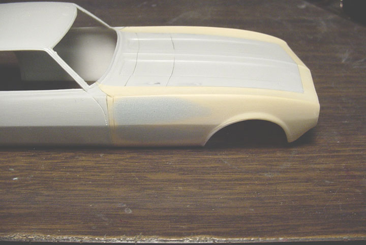
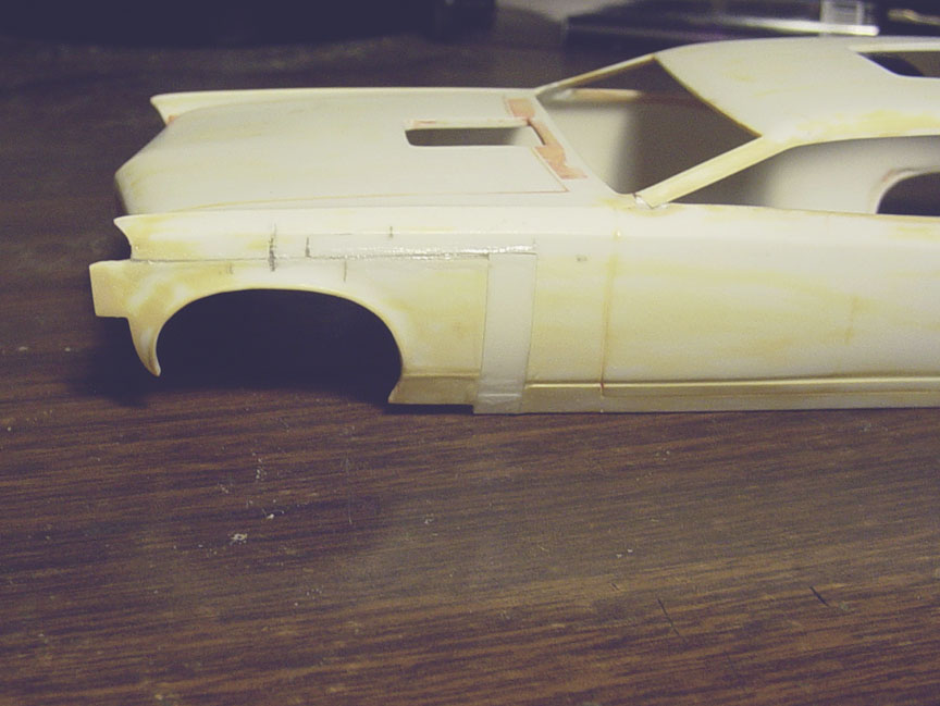 After comparing photos to the MPC Mr. Unswitchable to the 1:1 Mr. Unswitchable,
it was obvious that the front wheel well is a couple inches higher than stock.... (I'm guessing to make the body sit lower).
2 inches were cut out from the height of the wheel well and a
5" patch panel from a donor body is used to fill.
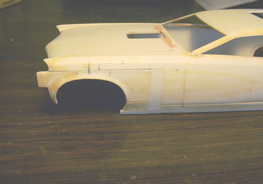 Also: a 2" filler piece is need to fill the bottom edge and all body lines will need to be cleaned up.
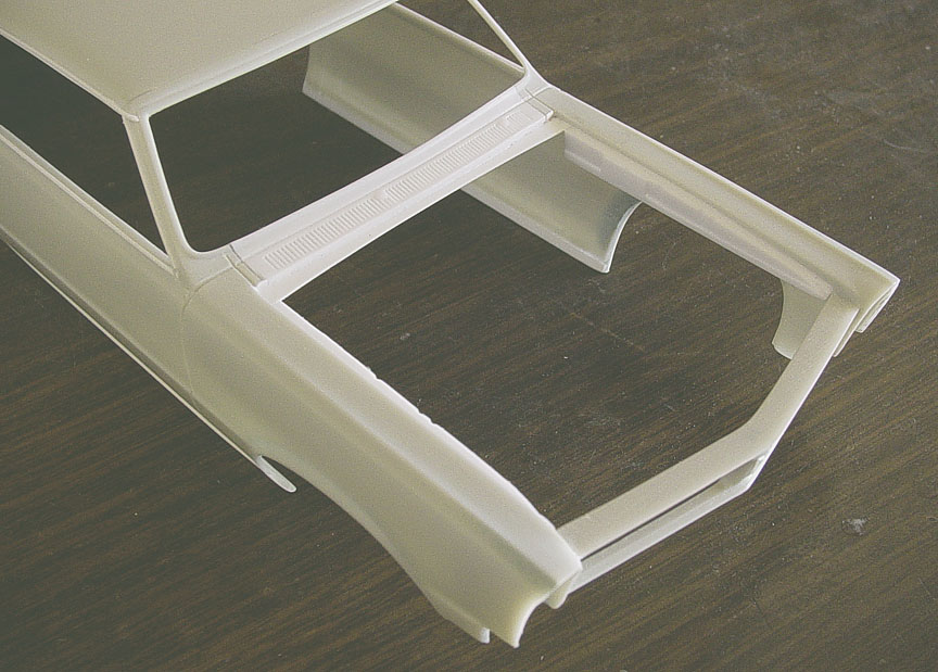
 Plastic strip was used to set the cowl farther back 2 1/2" , and the bottom curve of the window frame
needs to be re-shaped.
 The rear wheel well needed to be filled in because the rear wheels are moved more forward than the mpc kit is.
A piece of the donor GTO body rear 1/4 panel was used to fill it in and has the same curve as the new body.
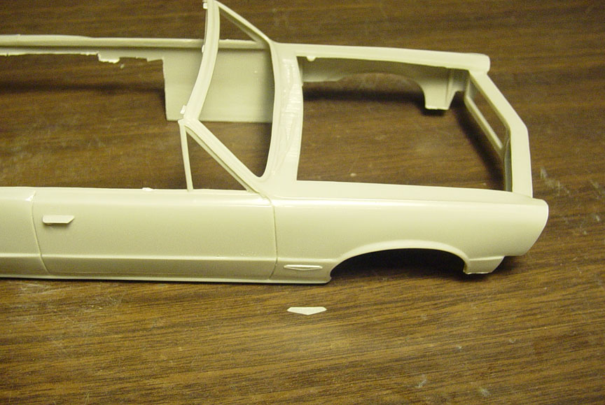
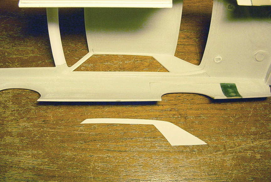
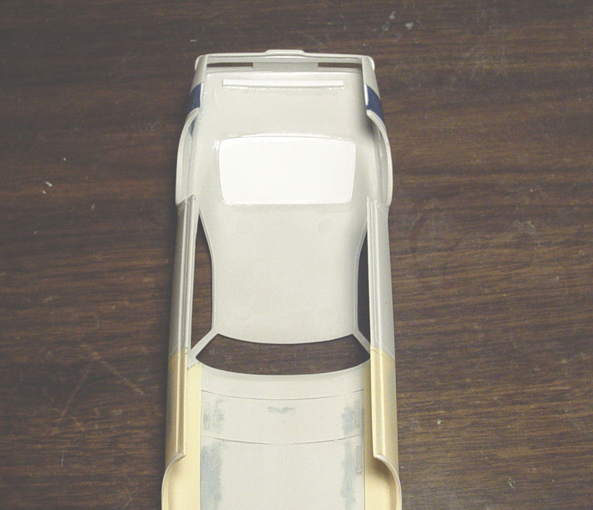
 After closer inspection, I see that the 1:1 car had the top of the door panels run straight.
I want to fix this before starting the rear wheel well alteration, so....040 X .040" strip was glued to the top of the door panels.
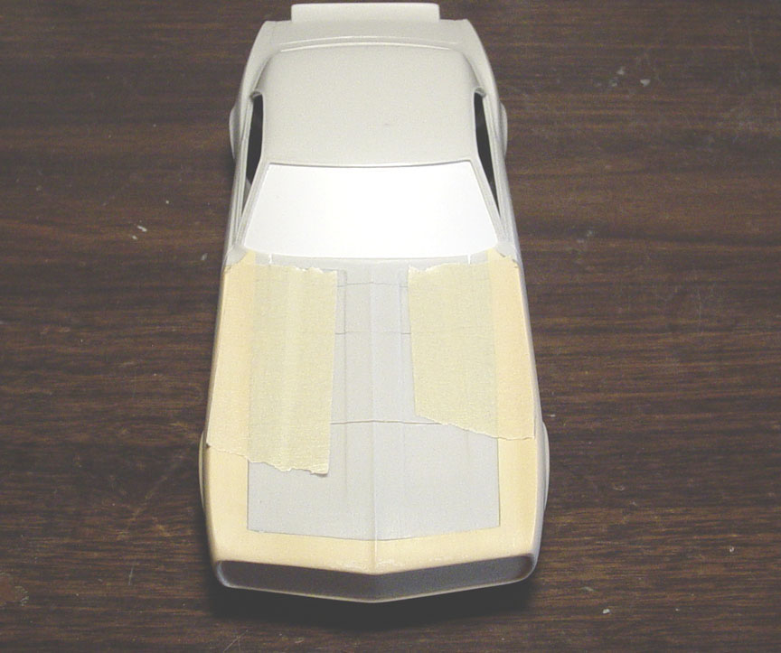
 Masking tape was used as a guide along the top of the door panels and will aid in applying putty,
to make the top of doors straight.
 Everything cleaned up with new door-body separation lines.
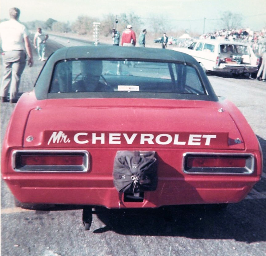
 After reading several magazine articles about the Mr. Unswitchable, they claim it as a 1967 GTO......Even
the mpc model kit was a '67 GTO !
But after studying photos of the 1:1 rear end, I see they were all wrong, the body is a 1966 GTO....... Not a '67 !
I guess I should have ignored the magazine articles (as they have proven to be wrong in the past) and paid closer
attention to the photos of the real car.
What this means is, that I'm going to have to pull the rear section off a Revell '66 GTO and graft it to the '67 GTO.
 After careful measurements, Both the rear clips werecut off.
 Because the Revell '66 GTO rear clip was 2" wider than the MPC Mr. Unswitchable body,
it seems it would be easier to splice the body instead of the rear clip.
A piece of .080 X .080" strip was used to widen the MPC body first and then the '66 GTO rear clip was glued to the MPC body.
Putty was used to match up the indifferences between the two bodies.
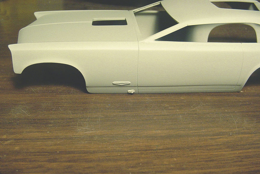
 Well I guess this solves the problem of the "lack of a GTO emblem" on the rear 1/4 panel.
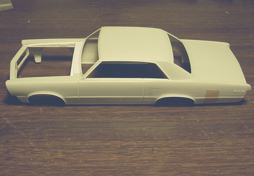
Now that the '66 GTO rear clip is on, it even looks longer & meaner, though it's the same length.
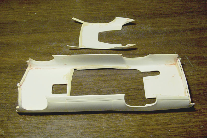
 The rear 1/4 panels needed to be pulled in 6 inches (according to the article), so the tail light area had to be
cut on an angle to allow room for the bend. You can really see the difference from the left "finished side" to the stock side.
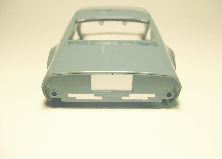
After pulling both 1/4 panel sides in, we need to fill the tail light holes.
 The 1:1 car dosen't have Tail Lights, but I want to keep the original GTO models Tail Light Lines to resemble
"Tail Light Block Outs", so the original lines were left alone while filling in the holes where the tail lights would be.
 Here you can see all the lines sanded smooth and the original Tail Light lines.
Screw Holes will be added later.
 Going back to the rear wheel wells...... a stencil was made from a side shot of the 1:1 car,
then brought into 1/25 scale and traced to Frisket Film, then placed on the body to re-shape the new rear wheel wells.
The rear 1/4 panels were heated with a hair dryer to bend the bottom of the 1/4 panels in 6 inches on each side.
The side body panels were also bent inward.
 .040" 1/2 round was glued to the edge of the rear wheel wells, and Evercoat putty was used to create
he fender flare.
 After breaking the A pillars (while bending the body and rear 1/4 panels in), pieces of metal pins were cut
and super glued on the inside of the A pillars for added strength. This may also help when gluing windows in.
 New drip rails are made with .020" square. These will later be sanded down to about .015.
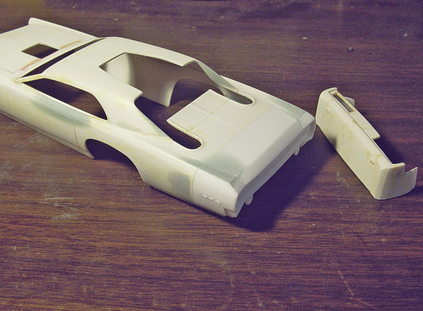
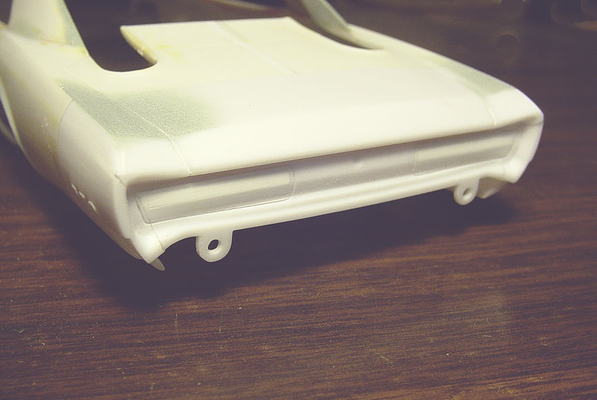
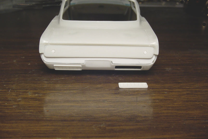
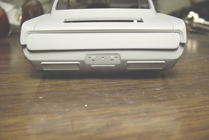
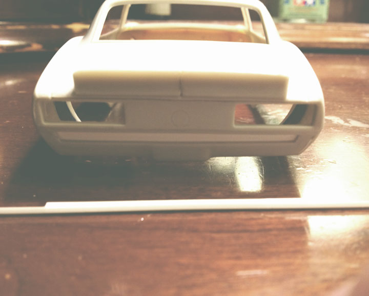
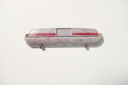
REAR BUMPER
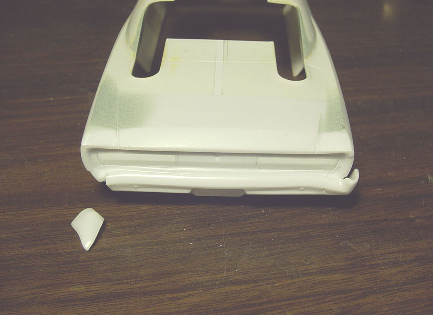 Now that the rear 1/4 panels have been altered, the rear bumper needs to be altered also.
The ends of the rear bumper was cut off and tilted to fit the new 1/4 panels.

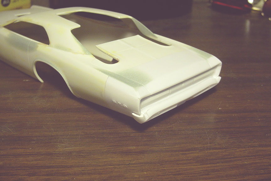 Both photos show the finished altered '66 GTO bumper against the body.
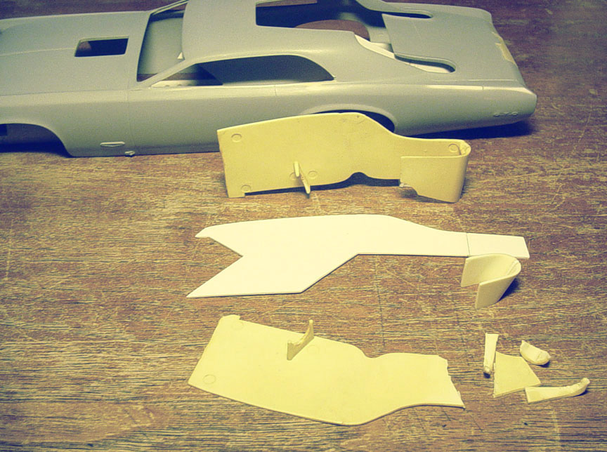
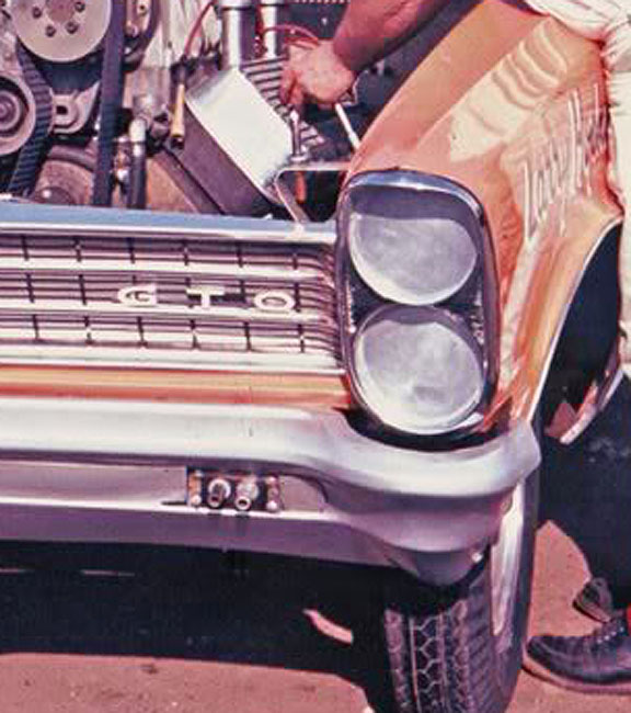
FIBERGLASS FRONT CLIP
The 1:1 car has a '66 GTO Metal body with a '66 fiberglass front clip and '67 GTO Grill Inserts.
Dick Jesse wanted a full fiberglass body, but they ran out of time.
Later the "Stretched Version" was all fiberglass.
 The GTO model's nose piece is 1 scale inch too short,
so another inch needs to be added to better fit the bumper.
The edges of the 1/4 panel Head Light shrouds were very uneven, so they were fixed with thin strips of plastic.
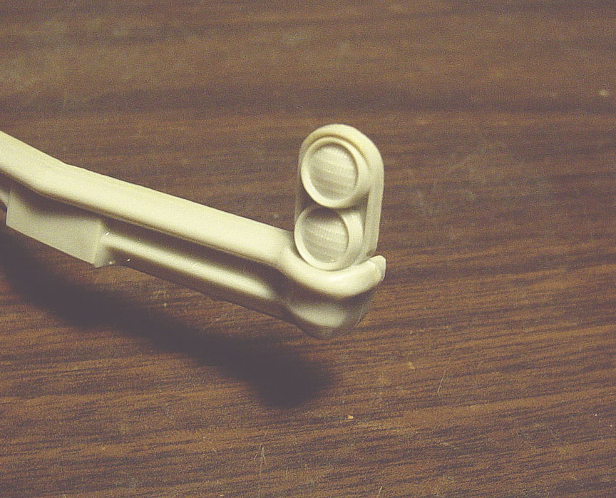
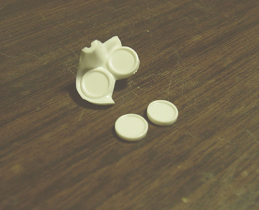
 After altering the bumper like the 1:1 car, the licence plate area was removed and deep recess was filled
with thin plastic. The stock head lights were then drilled out and a hole punch was used on .010" plastic sheet to replicate
blocked-out head lights.
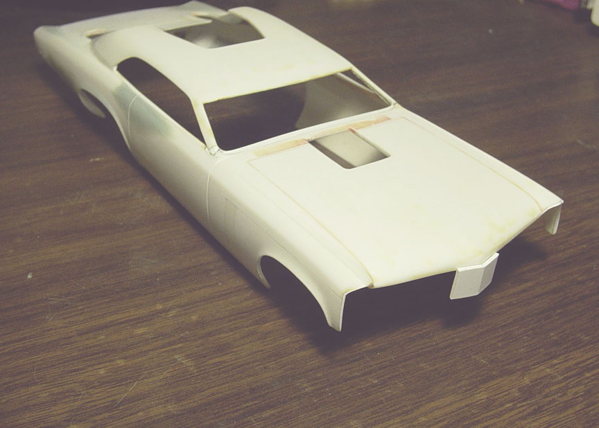
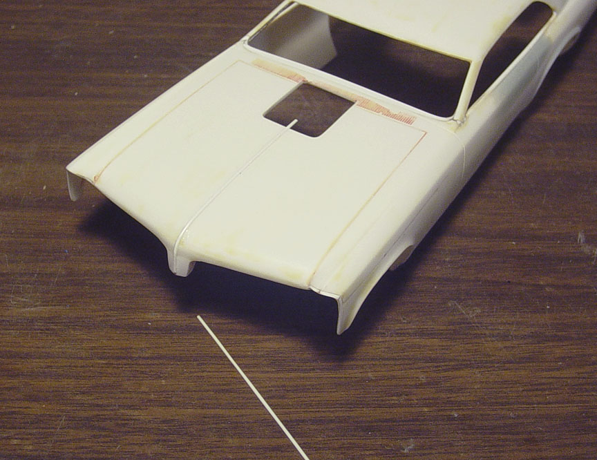 The raised crease on the center of the original hood was too short and too thick, so it was sanded off
and new .030" half round was used in it's place. This will later be sanded to resemble a sharp V-shaped crease.
 In keeping tradition with the original mpc Mr. Unswitchable, The hood pins from the trunk lid were cut off
from the "left over rear clip" and sanded down to the thickness of only the hood pin.
 The PONTIAC badges from the AMT '65 GTO were cut off and carefully sanded down evenly by hand.
 Both the Hood Pins and the Pontiac badges were glued to the body on both sides.
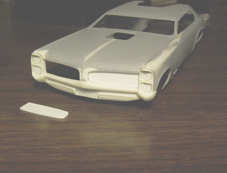
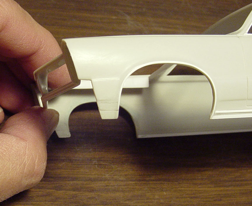
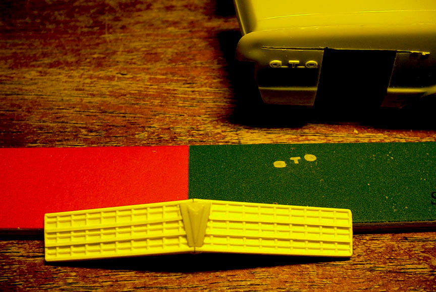
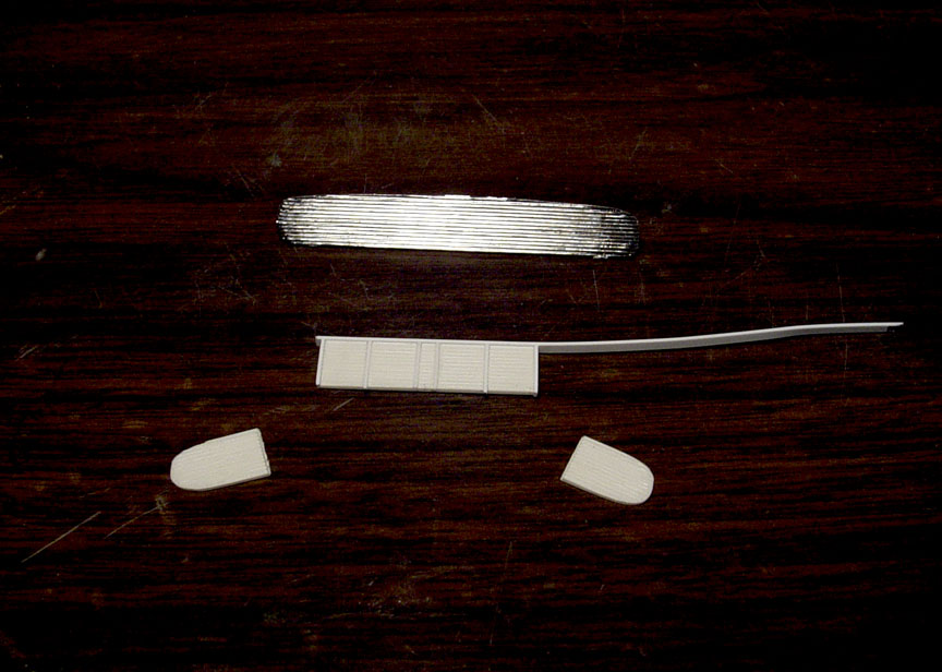
 The Mr. Unswitchable GTO had a fiberglass '66 GTO front clip with '67 grill inserts.
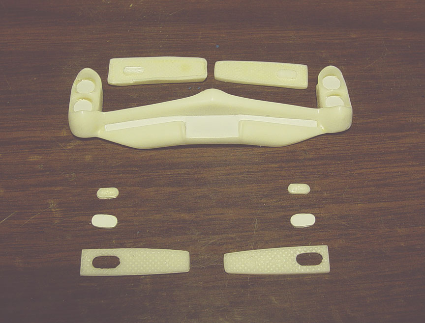
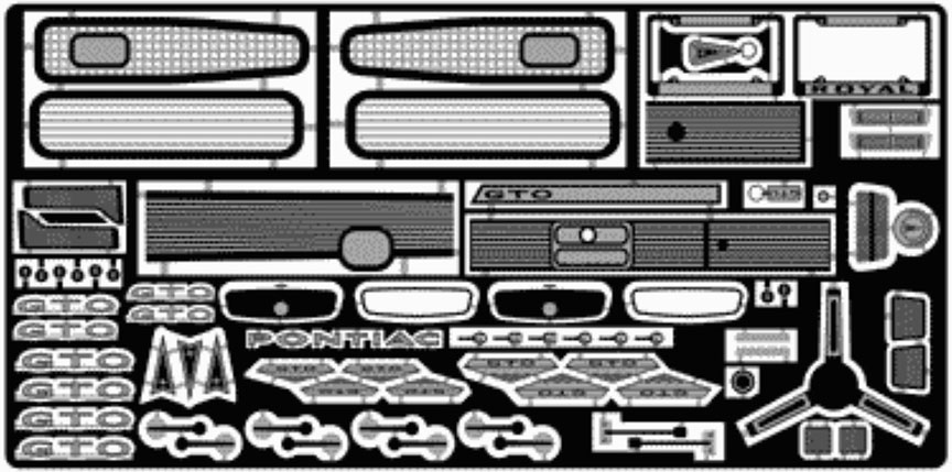
The MPC '67 GTO comes with 2 separate grill inserts..... (I can't figure out why?), but to make this "stock grill" look like a
fiberglass grill, we'll need to make some changes !
The
original grills were removed from the bumper and the 2 -"spare kit" grill inserts will be used, as they look to be the
correct size. First, the grill holes for the marker lights
need to have the holes filled as they are too large,
then the marker lights were cut off from the original grills and sanded down to make them smaller.
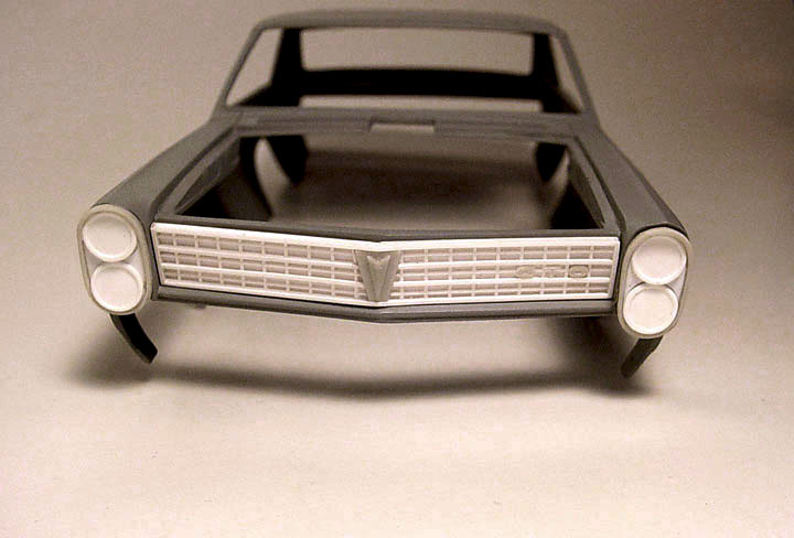
 Since the front clip is supposed to resemble a fiberglass front end, the bumper and head lights
are molded to the body. New "Back Panels" for the grills were cut from .040' sheet plastic.
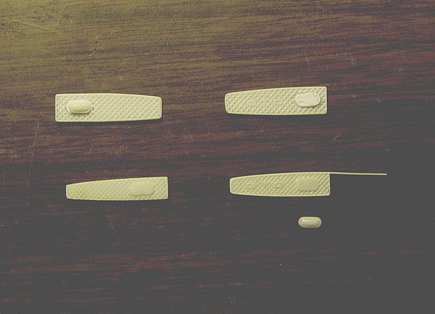 After test fitting the new "spare kit grill inserts", I see they need to be even smaller (about 2 more inches).
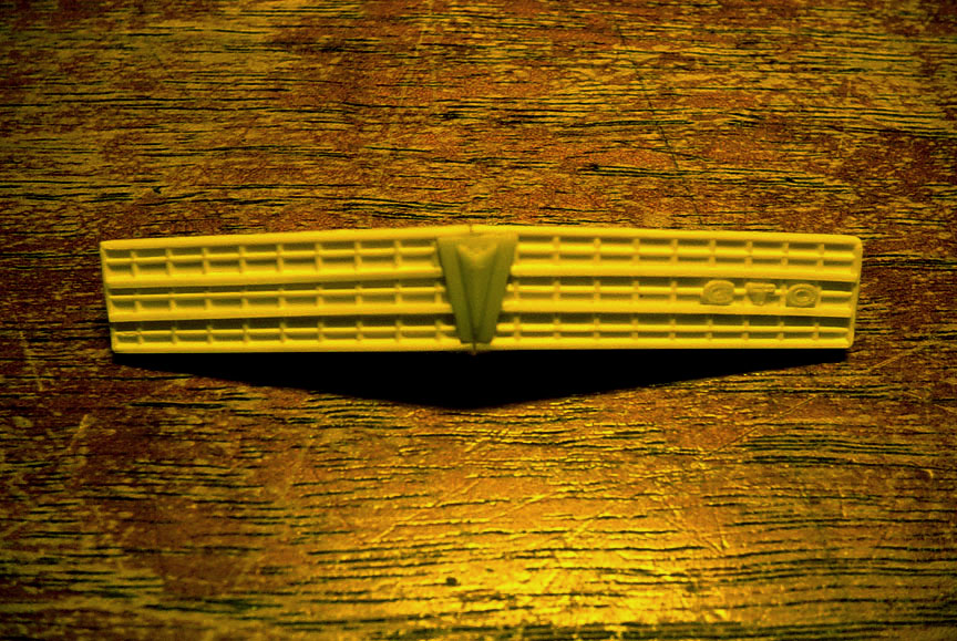
Since I need to make them smaller, I'm going back to the original grills to use, mainly because the GTO letters are raised.
.010 X .020" strip's are added to the grills for a new edge.
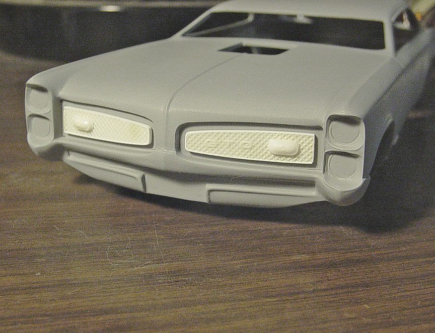 The new '67 GTO Altered Front Clip with correct '67 GTO Grill Inserts !
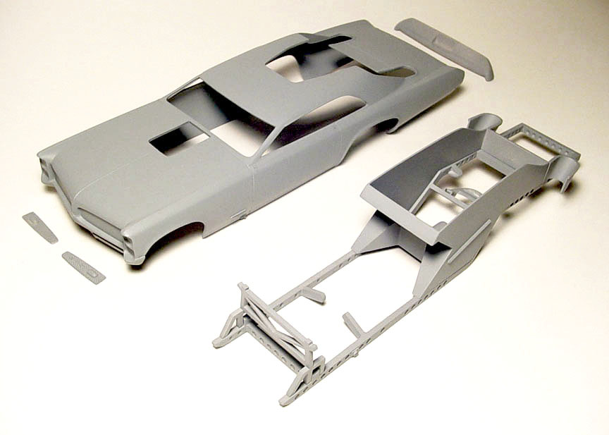
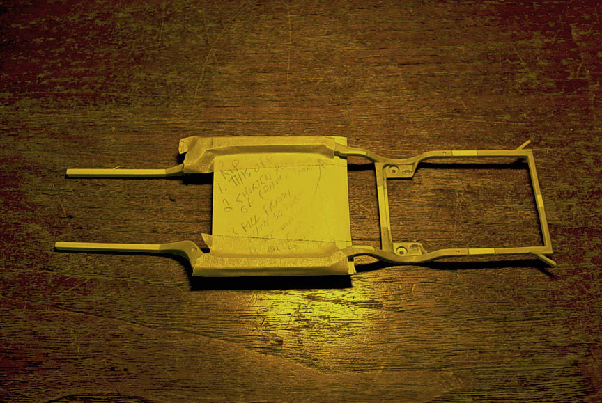
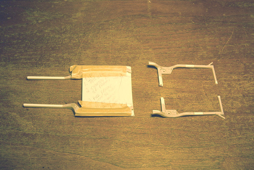
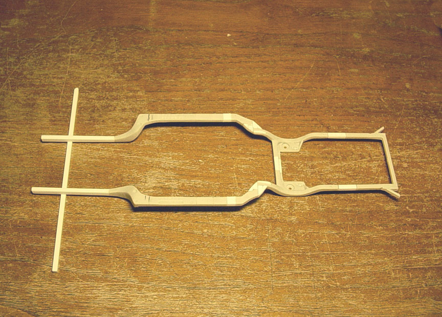
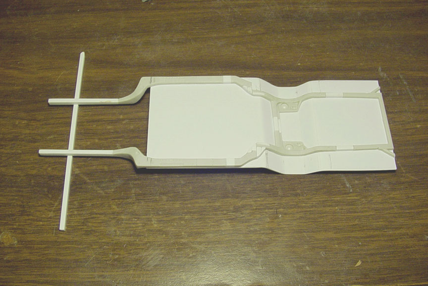
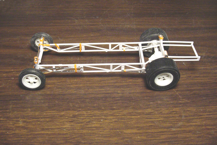
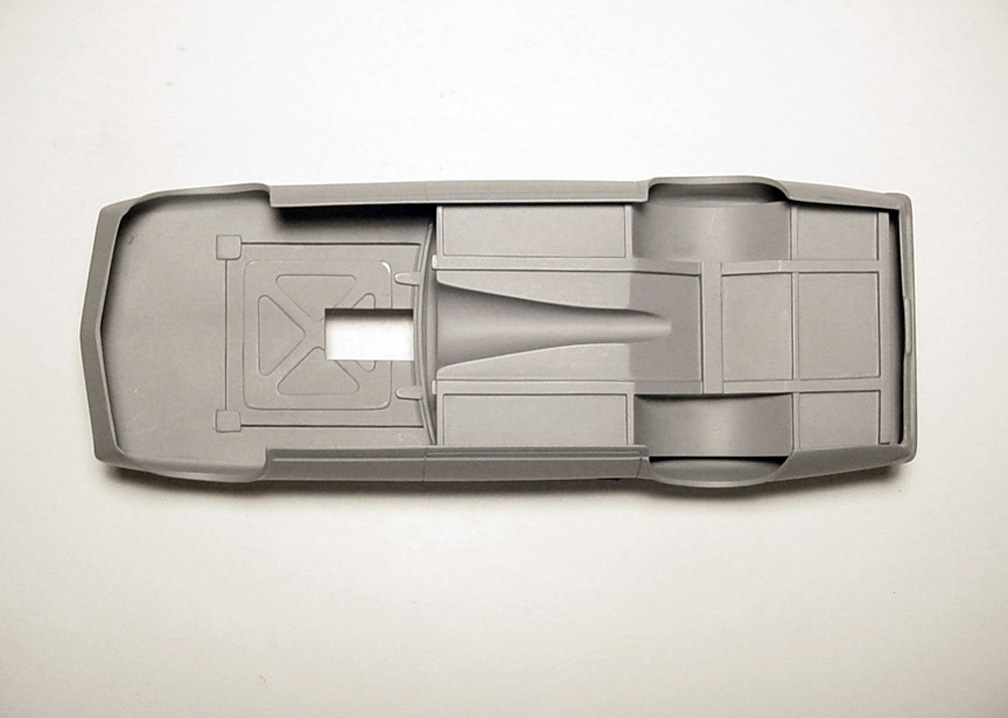
FRAME
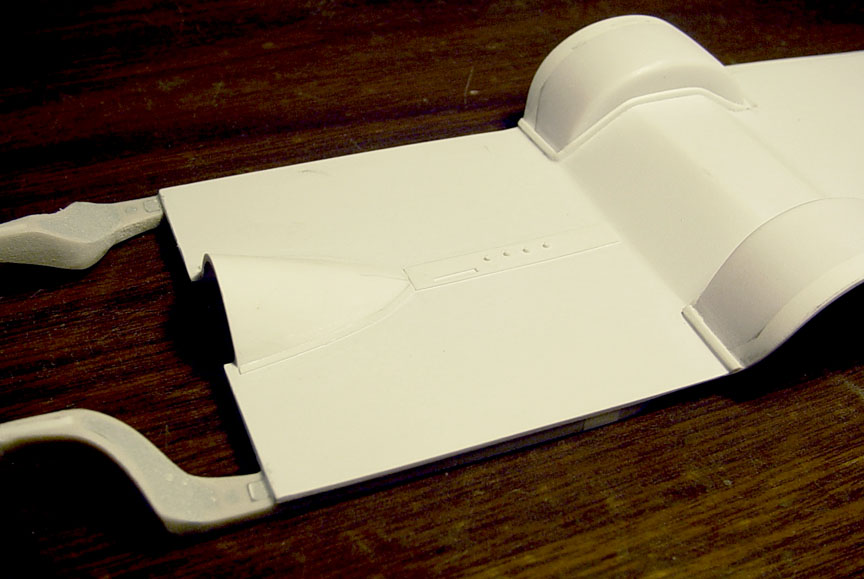
 The Mr. Unswitchable "swiss cheesed" frame has "Lightening Holes" in it and I want to try and replicate that
in scale !?!...... After a long decision, I came up with this idea to simulate the "Lightening Holes".
(The frame rails cannot have direct holes all the way through it, as it wouldn't be able to come out of a mold)
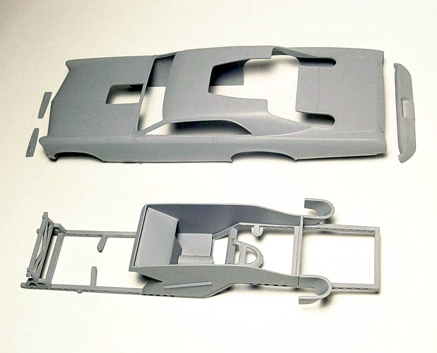
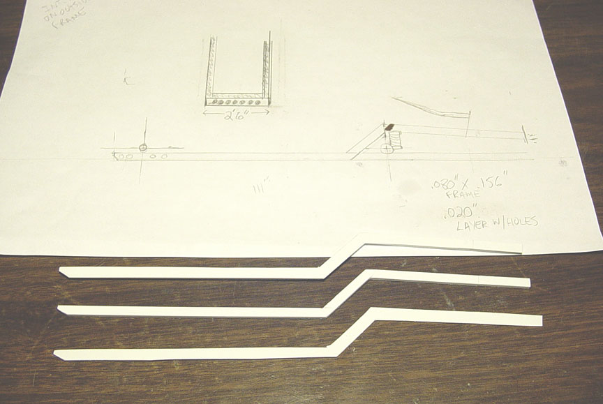 A diagram was made by measuring out the wheel base and looking at photos of the real frame.
.080 X .156" Square tube was used for the main frame rails. The frame rail was then copied on .020" sheet.
Then the .020" sheet was tack glued to the frame rails and sanded down evenly to match the original main frame rails.
 The .020" sheet was then removed (peeled off) from the main rails, and now the tedious part
of drilling all those holes in the .020" overlay. These new frame rails will now have pilot holes to resemble actual holes.
*These holes can be drilled all the way through by the builder or left to be painted black to simulate holes*
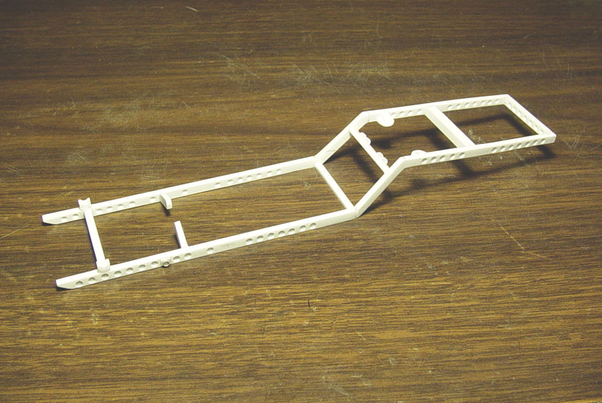 Didn't take photos of every step to the 100% scratch built chassis, as it would take up too much room.
So here's a basic run down.....
1. Five cross members were installed and the front and rear cross members were also "swiss cheesed"
2. Motor Mounts were set to correct height using a Revell '66 GTO Engine. (other Pontiac engines can be made to fit).
3. Shock Mounts were scratch built and installed.
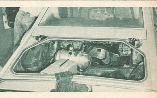
4. A 210 volt outlet was used on the 1:1 car to start the engine from a spare battery, it was scratch built from alum. & plastic tube.
5. Cheater Blocks were installed to set the front suspension
*This can be removed after you set the front suspension or leave the axle glued to it* ?
6. Guides for the rear suspension Control Arm were installed to the middle cross member.
7. A block was installed on the body's interior trunk lid to hold the frame in place.
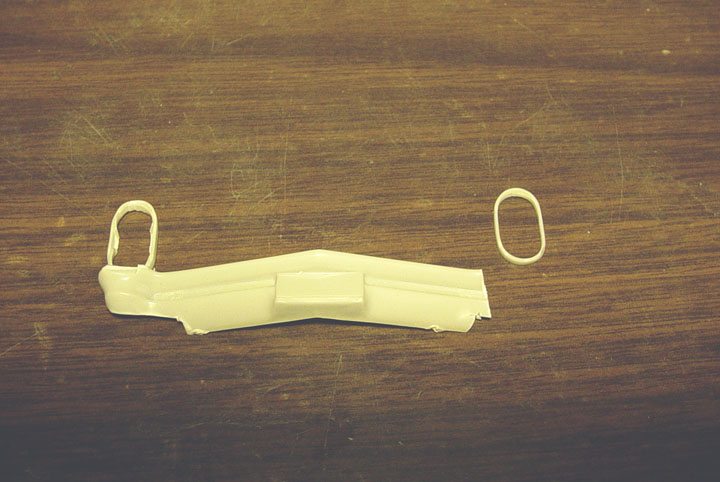
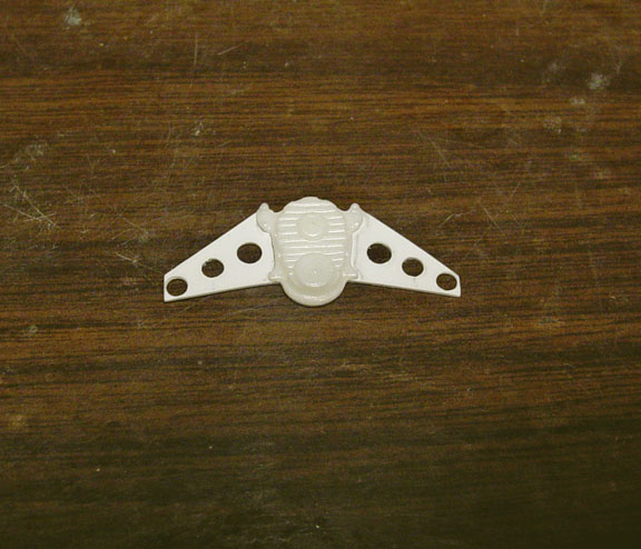
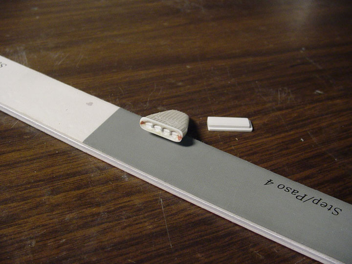
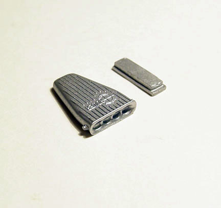
'58 CHEVY IMPALA CONTROL ARM
 Although the magazine claims the rear Control Arm is from a '58 Pontiac.
After asking around and doing some extra research, I found out the the magazine was wrong.
The Control Arm from a '58 Chevy Impala.
Checking the Amt/Ertl '68 Chevy Impala Control Arm, I decided to make a better one from scratch.
 The new '58 Chevy Impala Control Arm is 100% scratch built.... and a photo-etched bolt head was added.
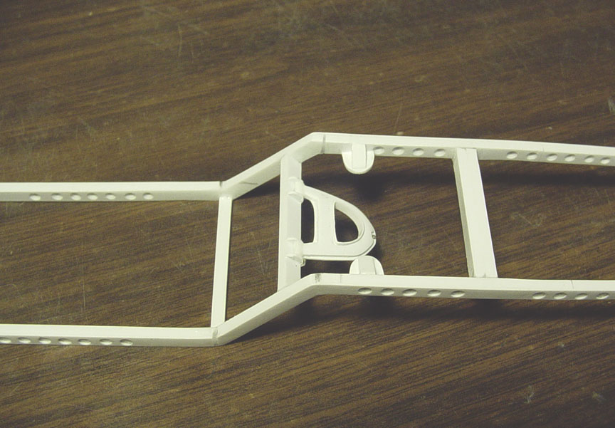
 Here's how the Control Arm looks mounted to the guides on the frame.
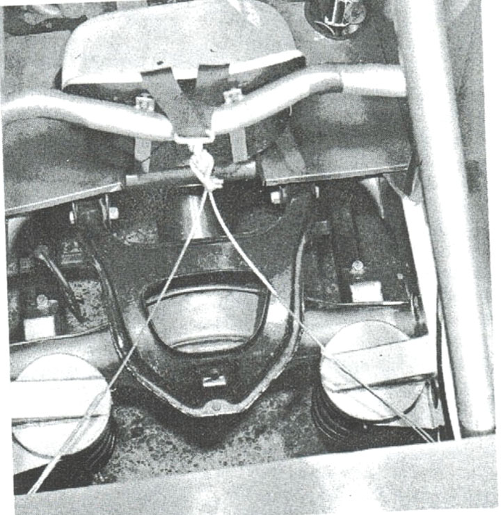
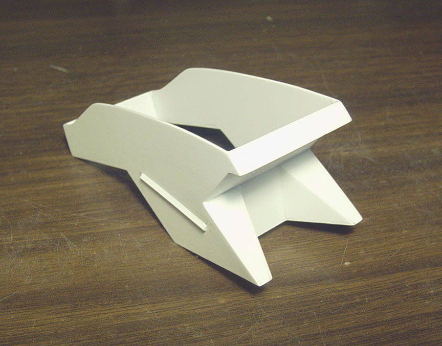
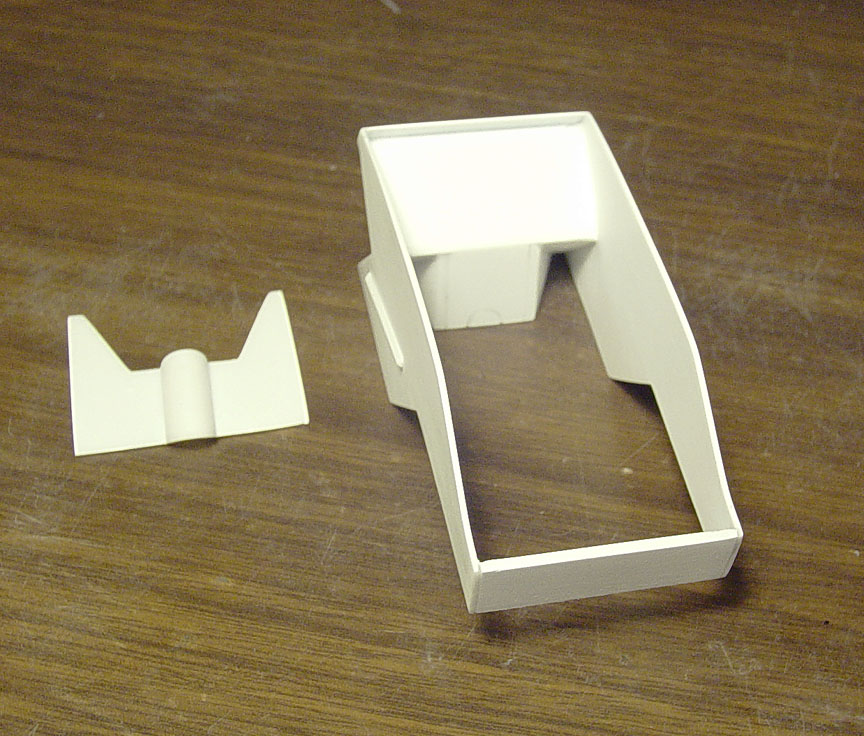
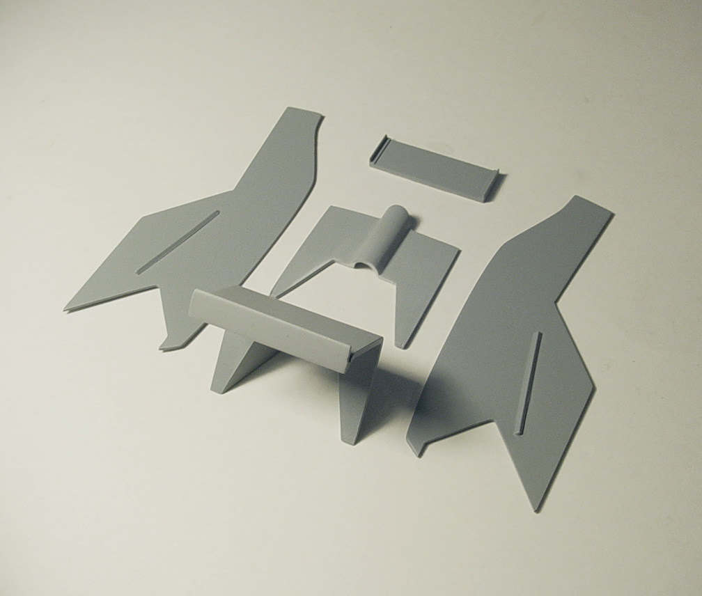
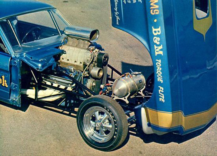
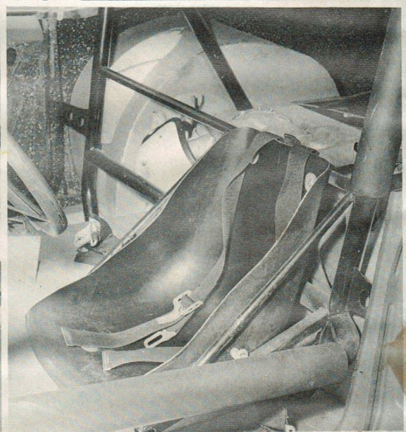
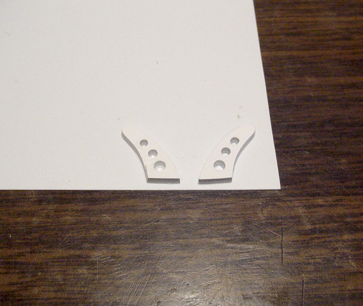
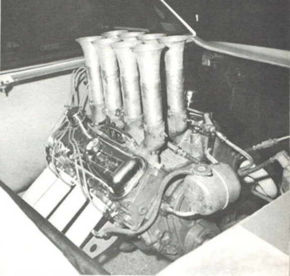
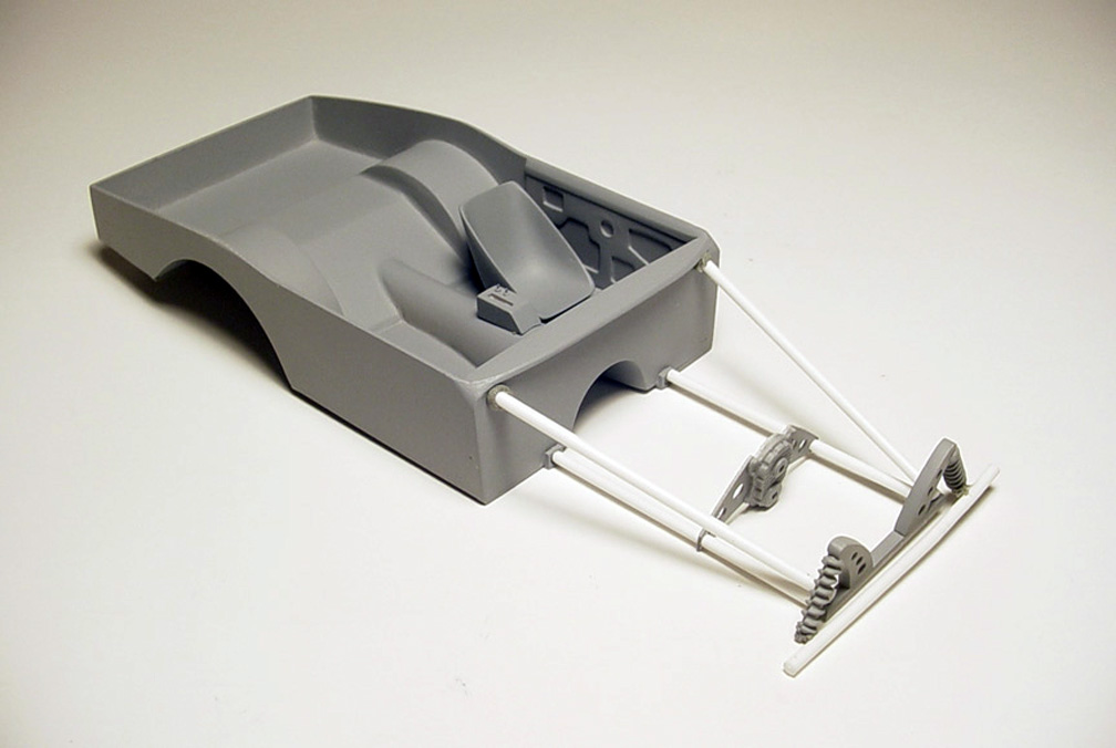
SHOCK TOWER
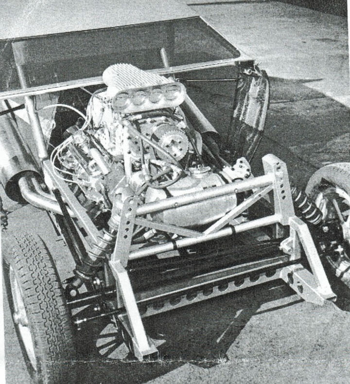 An unusually tall Shock Tower, this will obviously have to be scratch built !
 Looking at the photo makes these parts look like they were just thrown together, far from the truth !
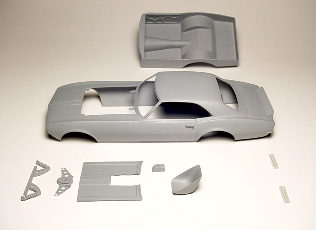
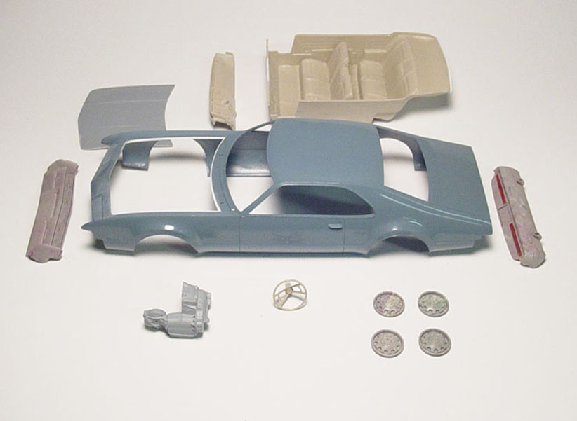
The entire model (Body, Frame & Interior tub) had to be mocked-up with slicks and tires using our Speed City
M&H Racemaster 16" Slicks and our Goodyear Blue Streak Front Racing Tires to set the ride height.
Then .080 x .080" square tube were all measured and made to fit.
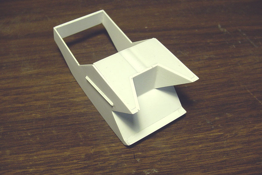
The lower tower supports were made first and the top tower (with shock mounts) was made last.
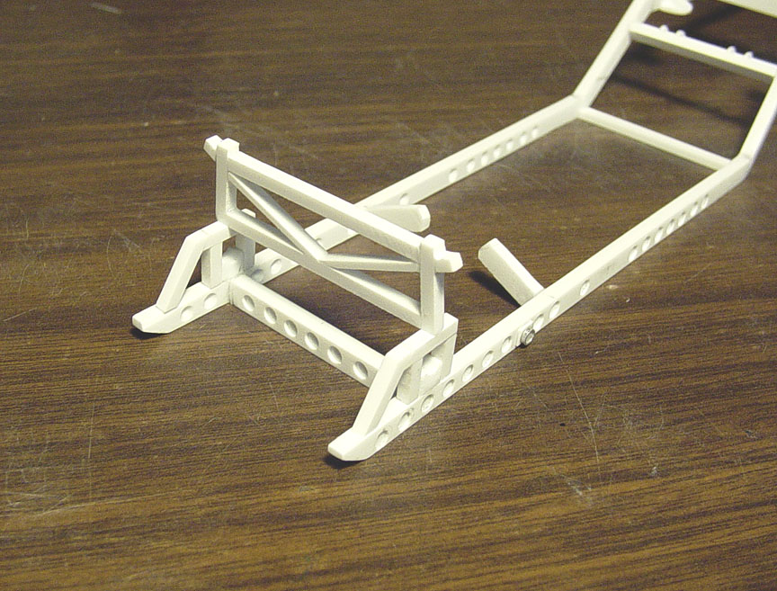 Here's what the Tower will look like when assembled.
These pieces will be cast separate due to casting reasons.
Front & Rear shocks can be made from scratch or you can use the Revell Thunderbolt Front & Rear Shocks.
Notice the cheater blocks for the axle. These "Cheater Blocks" can be used to set your shocks and then removed (or not).
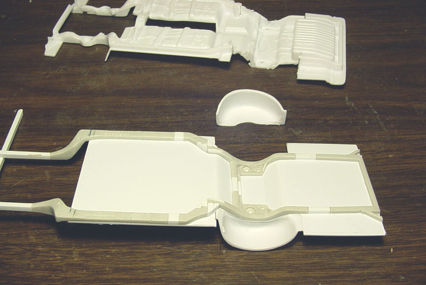
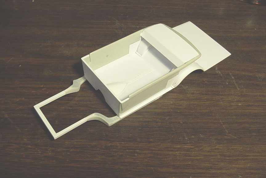
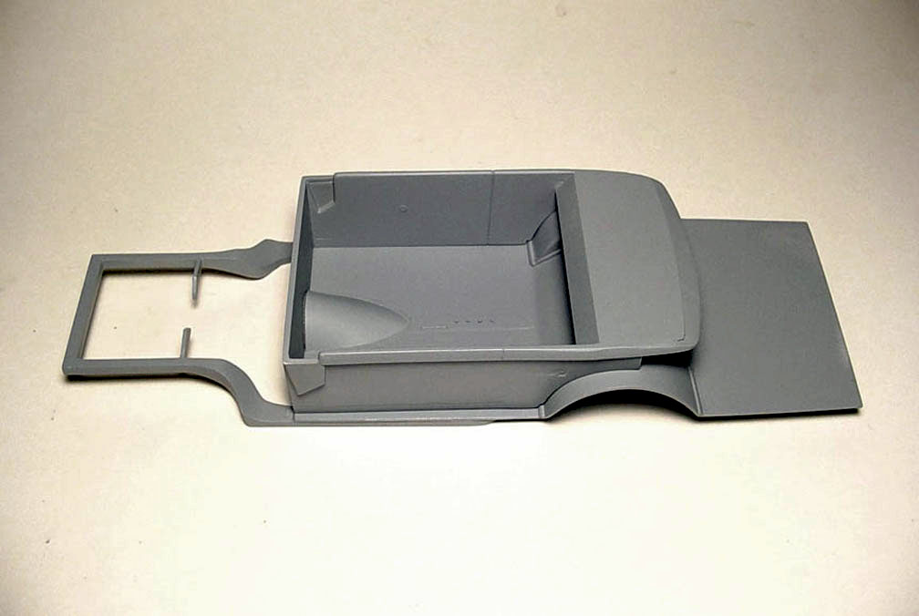
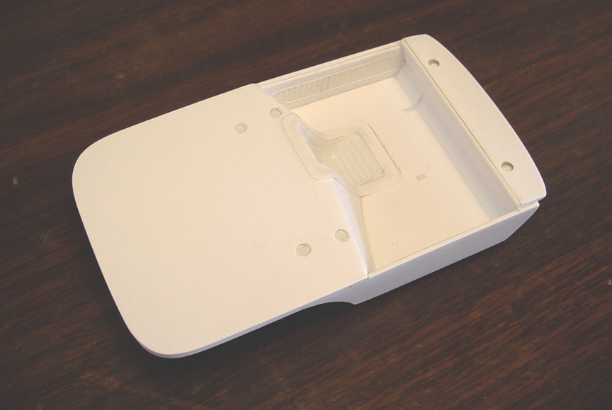
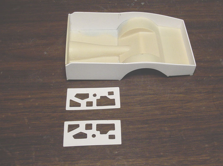
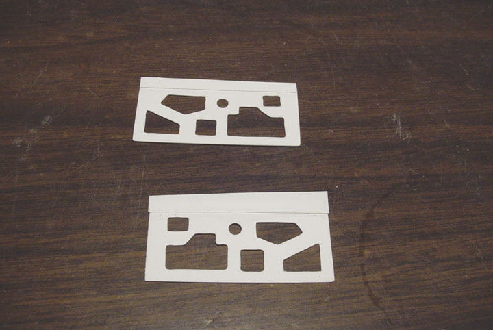
INTERIOR TIN
 With only a few known "Interior tin" photos, were going to try to replicate the tin with sheet plastic.
 The original MPC interior tub pieces (cream color) will not fit for this project and doesn't resemble the 1:1
car's interior tin anyway. Masking tape was used to outline the area between the frame and the top of the roof,
it was then penciled in and the tape was placed on
.030" sheet. That was then cut out and re-shaped to perfection.
Then another side was made to match.
The "Zoomie Funnels" were used from the original MPC interior parts, because they already had the curve needed.
But, they were re-angled to lean back about a 50 degree angle.
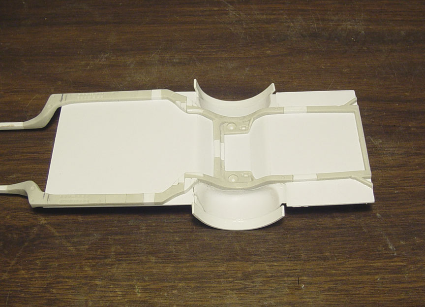
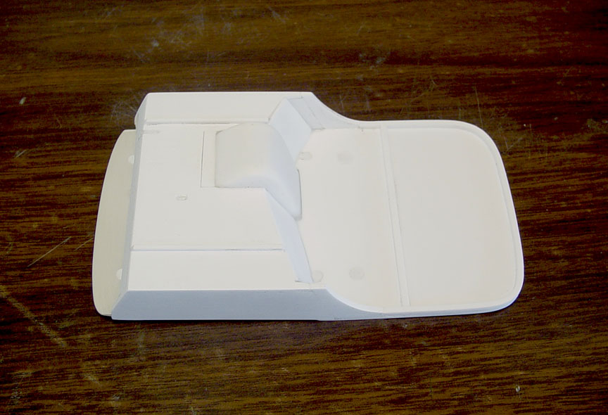
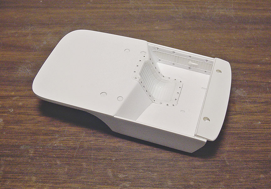
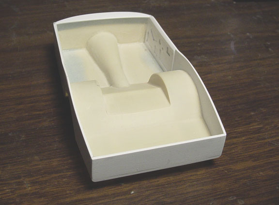
 Didn't take photos of every step to the 100% scratch built Interior Tub, as it would take up too much room.
.060, .040 and .030" sheet plastic was to used to make this correct Interior Tub, painstakingly built from photos.
A square strip was made as a guide for the exhaust tube.
*K&S Aluminum Tube 5/16 x .014" will be needed for exhaust tube*
 A Revell '51 Henry J floor was used for the floor as it had a clean transmission tunnel cut to fit the Interior Tub.
 Here you can see the close tolerances on the press fit.
FINAL TOUCHES
 Going back to the body, Some imperfections were sanded out and 6 photoetched Hood Pins were added
to the top of the doors and trunk. 14 "Screw Holes" were drilled into the "Tail Light Block Outs" and the hole in the hood
was also cut back to the cowl. The hood pins were painted over on the 1:1 car.
MASTER IS FINISHED !
UPDATE:
The 1-piece Interior Tub was too difficult to remove from the mold,
so it will now be in several easy to assemble pieces.

This new Speed City model will not only have the most accurate '65 GTO body ever made,
but will also have a 1965 TEMPEST GRILL (never seen in model form), AWB Chassis and Interior Tub.
BODY WORK
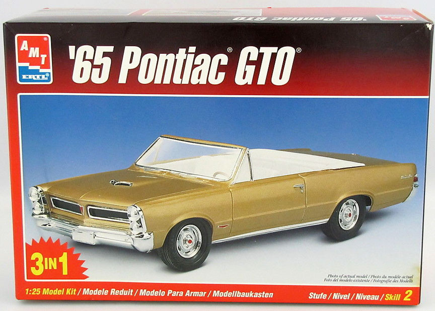 Starting with an amt/ertl '65 Pontiac "Lemans" GTO Convertible...... (which has a lot of flaws).
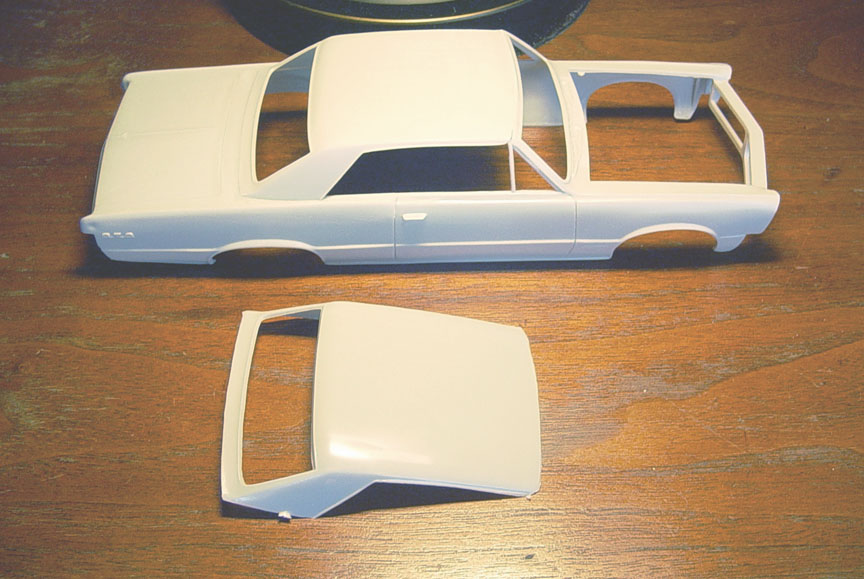 The ill fitting roof was carefully glued to the body.
There are several issues to tackle to make this roof look right, including the lack of window trim,
but we'll get to that later in this build. For the most part, I wanted to add the roof to the body to be more solid for the wheel alterations.
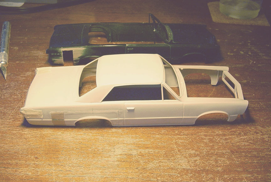 Several Magazine articles claim that the wheel base was moved 10 inches, so they were moved a scale 10".
Another painted GTO body was used for the patch panels. All GTO emblems and center crease on the trunk were taped off
as not to sand them by accident.
 The rocker panels on the amt GTO are too short, as you should be able to see the door line !
The model had the trim on the door line, so all the trim and wheel well lips were removed as the plastic body had a lot of
sink holes and it was just easier to remove everything.
3 scale inches were added to the rocker panels (later an inch will be removed) and half round was used
to re-make the bottom of the wheel well lips and the half round trim along the rocker panel.
 The 1:1 BRUTUS GTO was a metal bodied car, it did have cowl vents.
(Every resin body I've ever seen has the cowl vents filled in)....... That would be the easy way out,
but we want to make an accurate replica !
The amt '65 GTO cowl still has it's wipers and way too small vent holes, this would be too involved to clean up.
After looking at a Revell '66 Pontiac GTO, there were no wipers (only wiper mounts) and the vent holes were much cleaner.
The cowl was removed from the Revell '66 GTO and grafted on to the amt '65 GTO body,
making sure to match the window trim. All the trim on the side windows were removed and the entire body was re-surfaced.
 Corrected drip rails were added using .020 x .020" strip. and lower window chrome moldings were added....
(never before seen in resin or plastic).
 Inside of the body was sanded even and then thinned to about .040".
Weather strip molding was added to the interior of the roof and sail panel with hand formed .010" sheet.
 We now have correct window trim !
 The rain trougth was added to the bottom of the cowl using .010" x .125" plastic strip.
(If you plan to pin the hood, You can drill through the trougth and hood and then add your pin's).
The inner fender structure was cut off from the Revell '66 Pontiac GTO (The wheel wells were removed and altered to fit).
 The amt '65 GTO didn't come with chrome wheel well trim rings, so we added .030" half round,
re-shaped to fit the curve of the wheel lip and sanded the top flat to be 1/2" all around.... this took 4 1/2 days of intense labor !
The amt '65 GTO didn't come with chrome wheel well trim rings, so we added .030" half round,
re-shaped to fit the curve of the wheel lip and sanded the top flat to be 1/2" all around.... this took 4 1/2 days of intense labor !
 After moving forward (to do the headlights), I checked the bumper against the front quarter panel.
And it figures....another flaw in the amt kit..... The front rocker panel was too short.
A piece of the 1/4 panel section was removed from the spare '65 GTO body and about 4" was added to the Brutus body.
It was then cut down to 2-1/2" to match the bumper.
To review: We've added 30 extra pieces of plastic to make this body as accurate as possible !
HEAD LIGHTS
 Check the comparison between the 1:1 Brutus GTO and the amt '65 GTO kit headlight.
I've been thinking for days on how to make these head lights look correct ?
I scoured all my head light parts bins and came up with nothing..... at this time, I have no idea how to pull this off ?
 After looking through my model kit head light inventory,
I noticed that the Ed Roth Beatnik Bandit
After looking through my model kit head light inventory,
I noticed that the Ed Roth Beatnik Bandit
has the headlights (with a raised lip) and no bulging headlight......This "should" be a good piece to start with !?
Each head light was cut away from it's base and sanded smooth (round).
 Everything was removed from the inside of the head light leaving only a hollow trim ring.
The trim ring was then cleaned up and polished !
 .020" sheet was glued to the inside of the trim ring, for a insert between the headlight buckets.
 The "Beatnik Bandit" head lights were placed on an angle, with the tops leaning back...so the
head lights will be straight on the model. This had to be done because the head light bezels sit at an angle.
 We now have correct headlights (with block-outs)......... Compare them to the amt kit part.
1965 TEMPEST GRILL
 The amt model kit gives us a Pontiac "LEMANS" grill, but the Brutus GTO needs a '65 Tempest grill.
This is going to be a problem, since there has never been a '65 tempest grill done in model form before !
As you can see, BRUTUS had a '65 Tempest grill with an after market GTO emblem.
The plan is to make a correct grill...... somehow ?
At the time of writing this, I have no idea as how I'm going to do this either ???????
(It's too bad one of the photo-etch company's didn't think of doing a Tempest grill) ?
NOTE: After doing research I found out that both the Pontiac Lemans & Tempest's could be GTO's by using aftermarket markings from the factory or dealership.
 After a few days of looking through parts boxes I came up with nothing, then I looked through all my
vintage kits and found an AMT George Barris 1966 Buick "Villa Riviera" that had a grill that I could work with.
I soaked it in some easy-off to remove all the chrome.... Now I need to find a replacement grill !
 The '66 Riviera grill had to be cut in half and re-angled to fit the '65 GTO angle.
The Pontiac center emblem on the front of the body was too small to work with, but the Pontiac emblem from the
trunk lid was the perfect size and shape, so it was cut out from the trunk and hand sanded down to about .030"
and then
re-shaped to a V-angle.
 Next came the tedious task of press fitting the Pontiac emblem into the Tempest grill.
This has to be a perfect fit and no room for errors !
The mid section of the Tempest grill was cut out with a Dremel Tool, jewelers files were used to fit the new Pontiac
trunk emblem. After working all night.....It's a perfect fit !
 The 4 center bars were made with .020 x .020" plastic strip.
 I considered using a photo-etch detail set for the GtO emblem on the grill, but as you can see in this photo,
the GTO emblem would have been too much work to deal with removing the outside boarder of access metal scrap.
So, I went with using a GTO emblem from the rear of the quarter panel on the amt '64 GTO.
 To get the correct size GTO letters, a chunk of the rear 1/4 panel was removed from a '64 GTO 1/4 panel
and painstakingly sanded down to just the individual G....T.....and O letters.
 Testors Tube glue was used to glue the letters down,
because the letters needed some fill behind them and the Testors tube glue will fill the back of the letters or they would rip off during the casting process.....
(mold rubber would seep behind them).
 .010" X .20" strip was added to all 4 sides of the new Tempest Grill.
 For the first time in model history..... We now have a 1965 PONTIAC TEMPEST GTO GRILL !
CHASSIS
 Starting with a G.M. frame from an amt/ertl '68 El Camino (since they are modeled separately),
The frame was then cut in half and widened 6 more inches and the wheel base was moved forward 10".
The front section of the frame was removed and .100 X .080" square tube was used to replace the original frame.
The rear of the frame was also lengthened 10" to go back to the bumper.
 At this point, the frame wouldn't allow the slicks to fit, so the rear of the frame was cut off and cut in half,
so it can be brought in.
 10" were removed from the width of the frame and pieces of plastic were needed to be able to glue the
rear of the frame back to it's position.
20 individual pieces of plastic were used to fill and alter this new frame.
 .030 sheet plastic was used as aluminum sheet flooring. This was the hardest part of doing this chassis
and everything had to be pre-measured and bent for all the bends around the frame wheel well.
Ultra thin super glue was used to fill any gaps.
 After careful measuring, first the sheet plastic had to be removed from the interior floor.
Then the wheel wells from the Revell '66 GTO were cut out and made to fit the new chassis.
 .040 x.188" strip was added to the edge of the wheel wells so it can be shaped to fit the body.
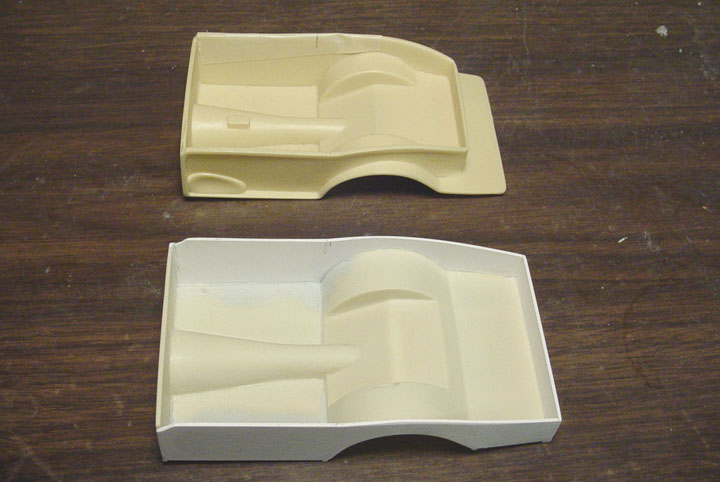
INTERIOR TUB
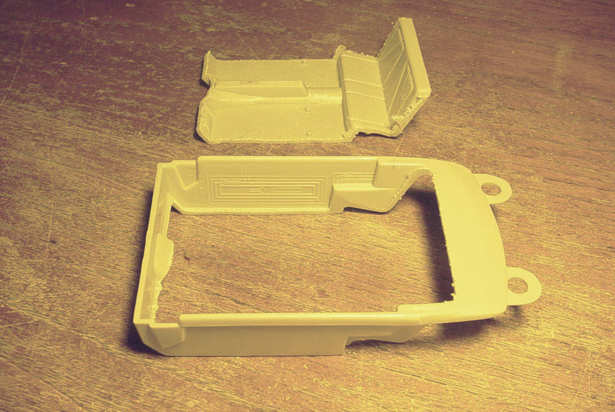 The stock floor was cut from the tub.
 To save time from taking a bunch of photos from every step, here's went into making the new interior tub.
1. All the door detail was sanded off.
2. Filler pieces were added to the rear seat section.
3. 3 scale inches were added to the bottom of the doors.
4. New fire wall was brought back 3 scale inches.
5. Old package tray was removed and new package tray was made from sheet plastic along with angled piece.
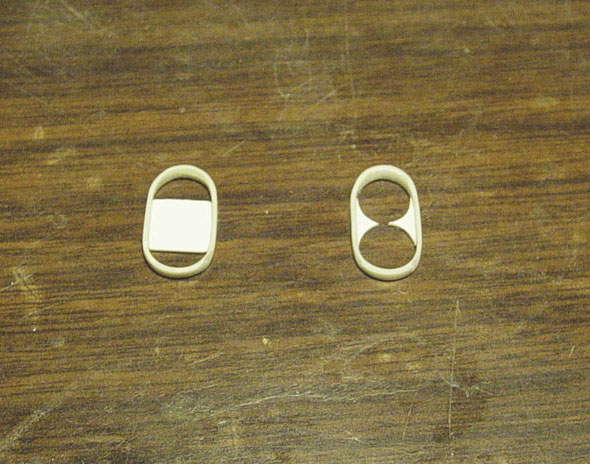
6. Not shown in this photo, but new door handle rings were made using photo-etched parts.
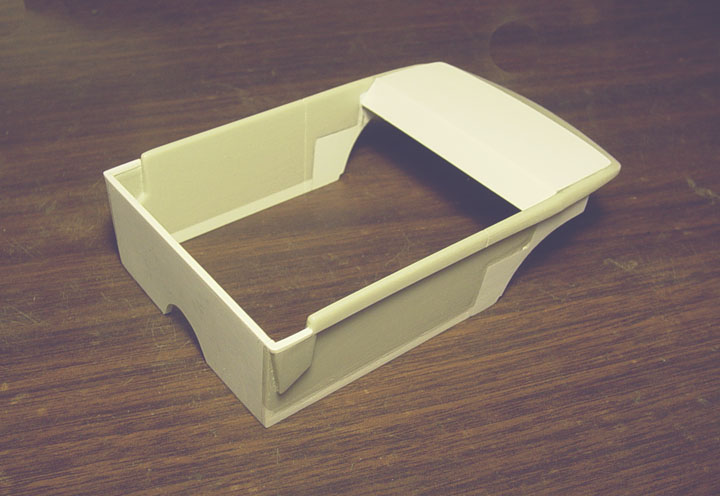
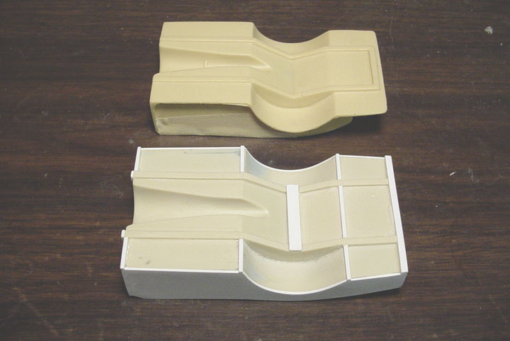
 Even though this is part of the chassis, it will also be the bottom of the Interior Tub !
1. Transmission tunnel was added using curved sheet plastic.
2. Mounting strips were added along the tranny tunnel.
3. A plate was made for the stick shift, 3 toggle switches and the rear "START BUTTON".
4. Plastic square tubing was added to the back the wheel wells, because it was too thin in those areas.
 Here's the fit between the Interior Tub and the AWB Chassis.
 Going back to the chassis to make Motor Mounts.....
A mock-up engine was assembled from the Revell '66 Pontiac GTO kit.
Motor Mounts were made from 40 X .188" strip, then cut to fit the Revell Pontiac 398 engine.
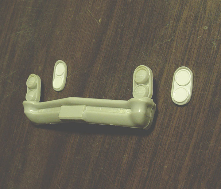
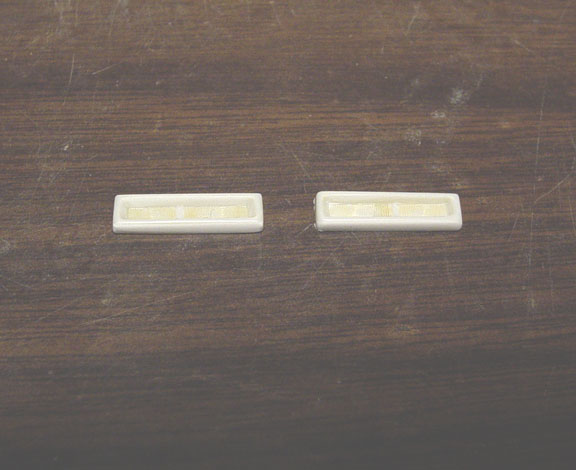
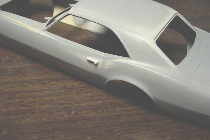
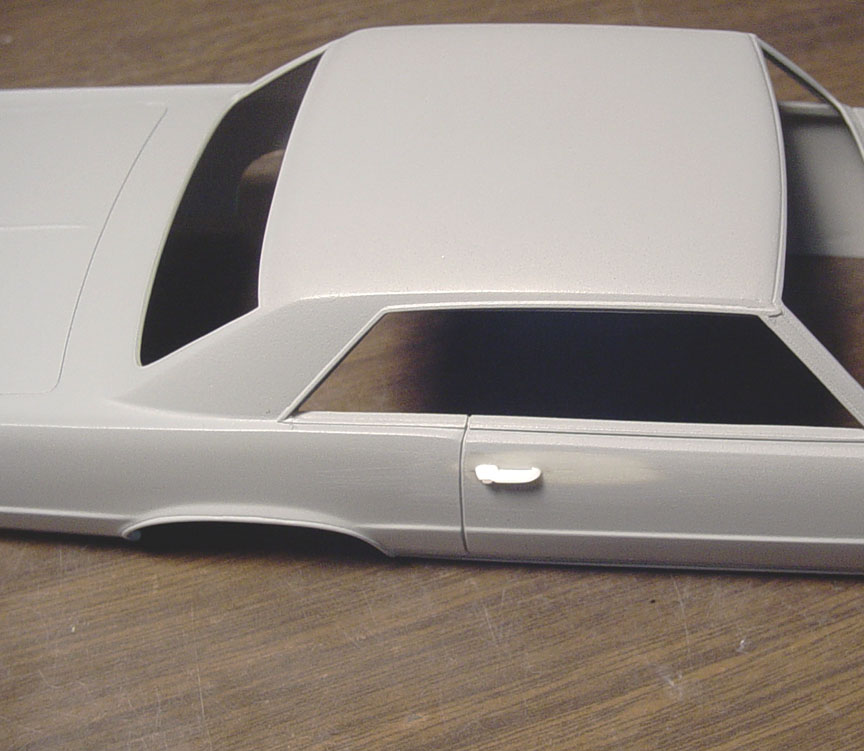 The last thing to do to the body is: To put in our "Speed City Signature Semi-Hollow Door Handles".
The door handles from the Revell '66 GTO were stripped of chrome and .010" sheet was cut to fit
the middle of the handle to act as a divider.
421 PONTIAC HEMI HEADS
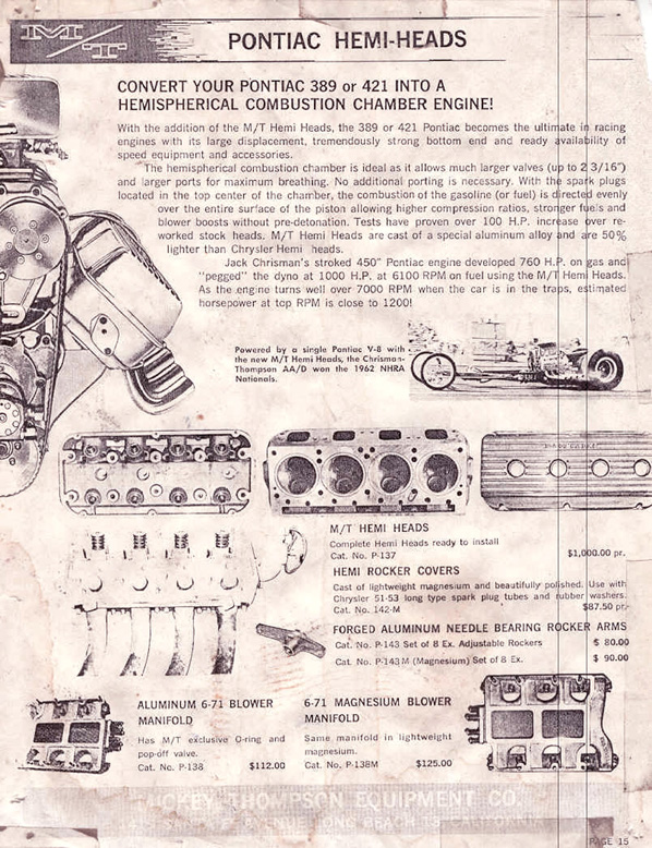 Here's a vintage flier for Mickey Thompson "HEMI HEADS" conversion.
 Starting with the heads from our Speed City Resin 392 Hemi Engine, a Filler Tube was added and a thin
piece of .010" sheet had to be added as a divider for casting purposes.
MASTER IS FINISHED !

"The only 1965 Pontiac Tempest GTO AFX ever made"
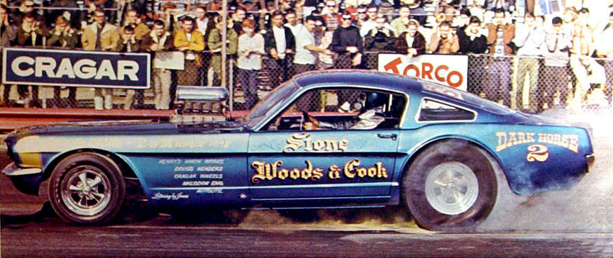
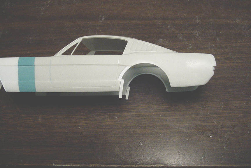
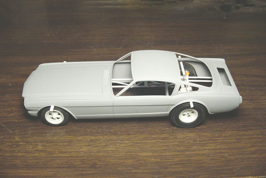
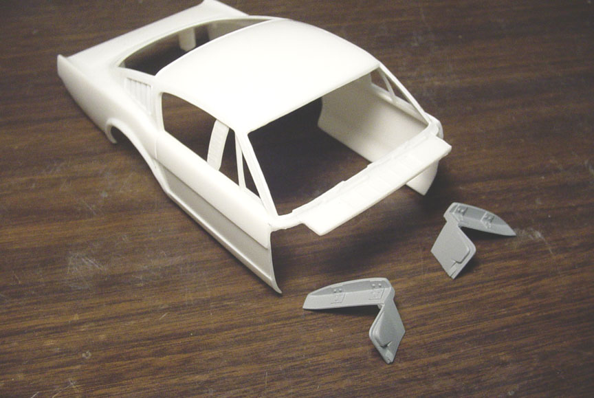
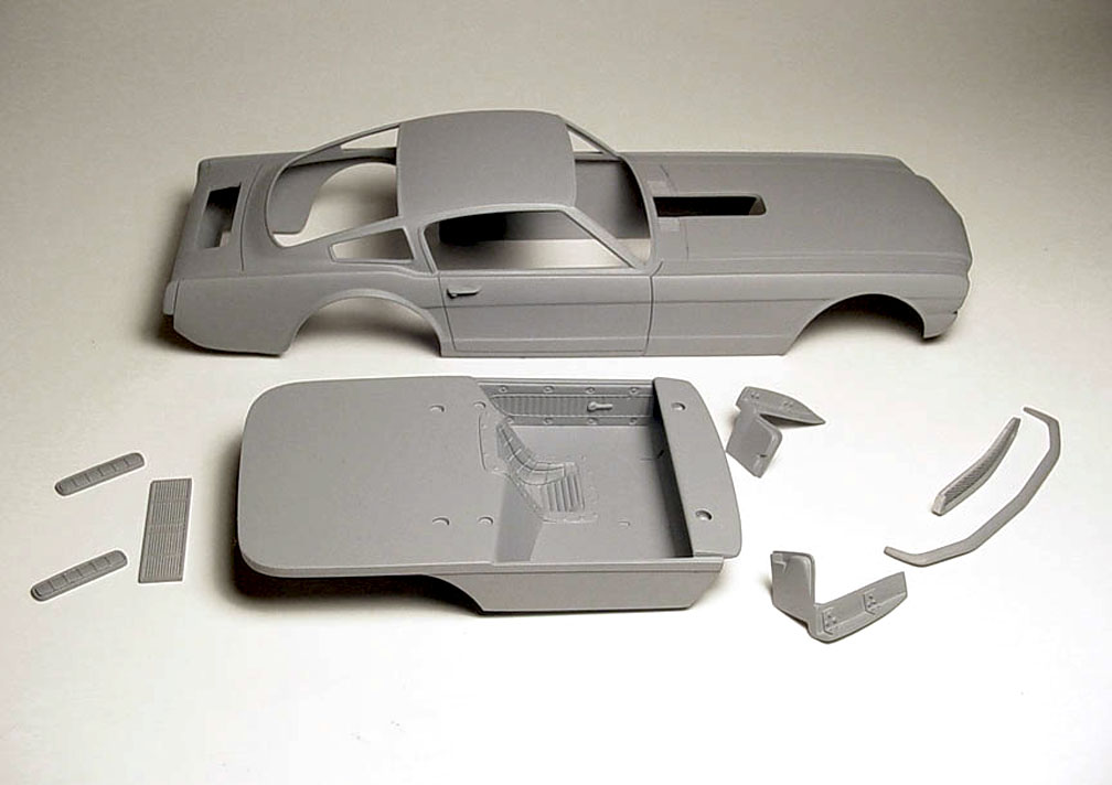
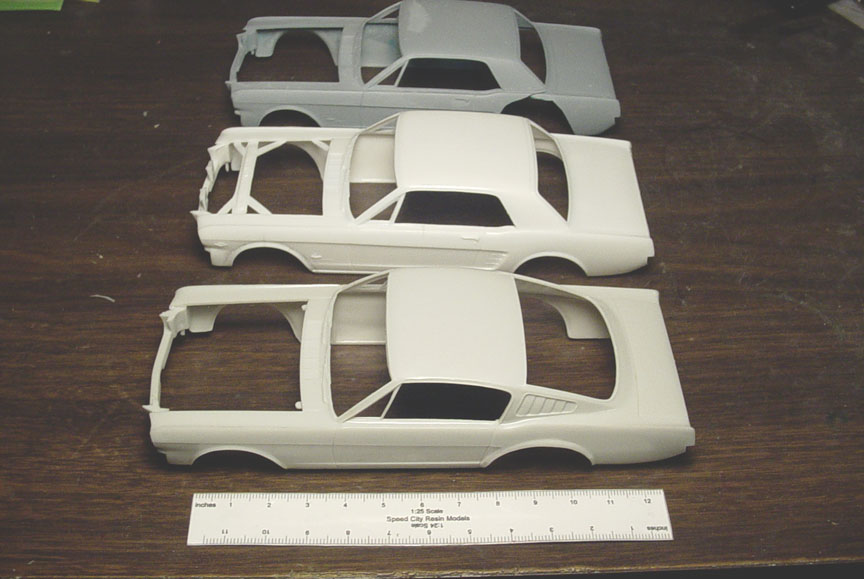 It was determined that 3 - AMT Mustang bodies will be needed to do the 22" stretch on the nose for the S.W.C. Mustang.
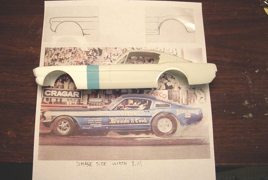
This 22" stretch info. was found in a few old drag magazine articles which stated that the S.W.C Mustang had a 118" wheel base.
The Funny Car body (in front) will be the #1 main body,
the white Coupe body will be used for the nose and the Blue Coupe Body will be used
for a filler panel between the two, all to make the stretch.
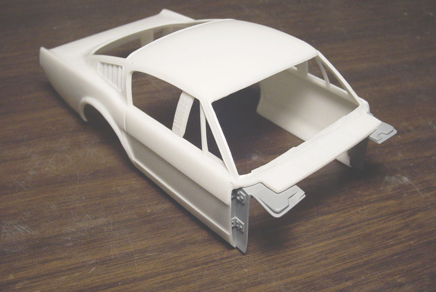
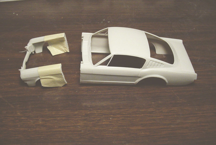 The main #1 Beige Mustang Funny Car body was cut just before the wheel well to give as much length as possible.
 The #2 white body (that will be used as the nose) was cut just before the A Pillar, to give the nose more length.
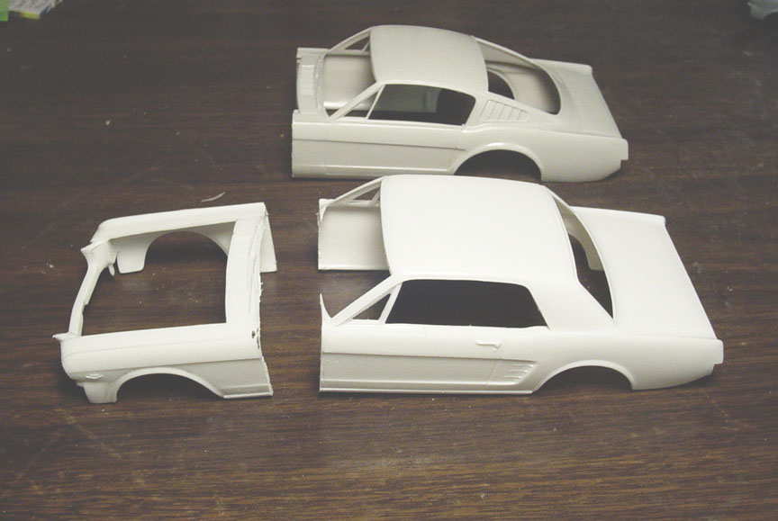
 The #3 blue body had 12 scale inches removed from the center of the front clip.
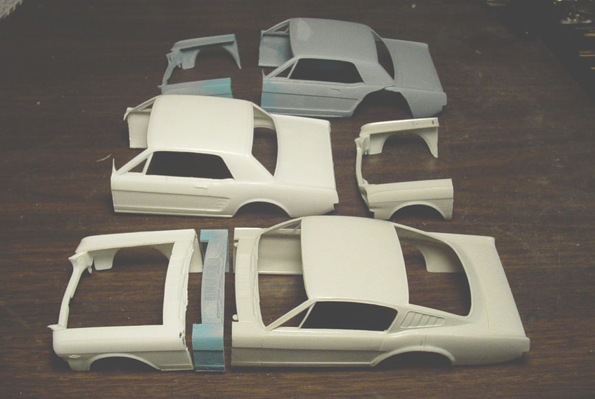 Here are the 3 body panels that will make the stretch.
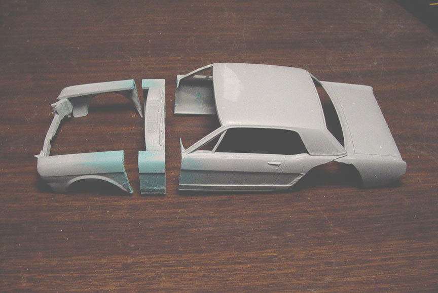
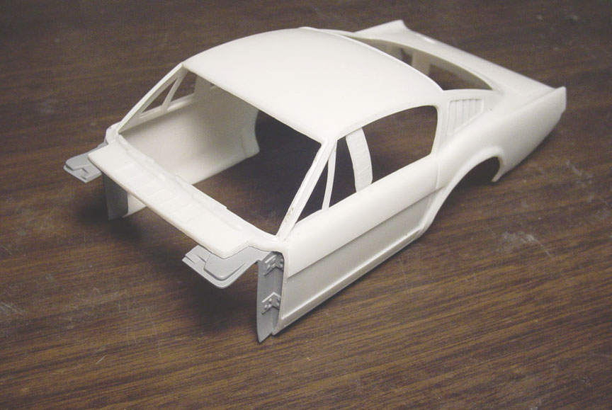
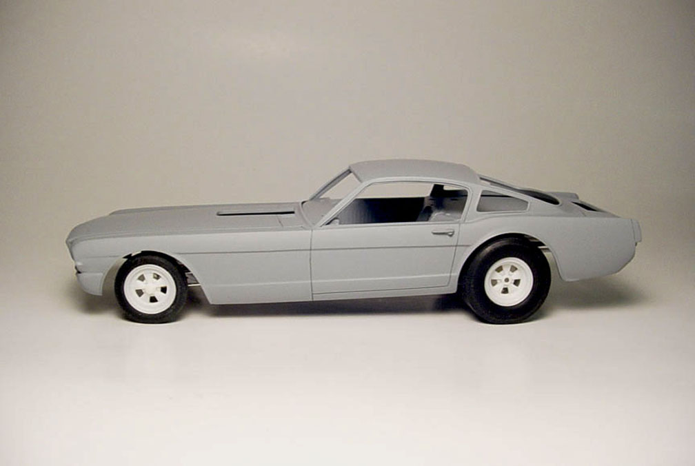
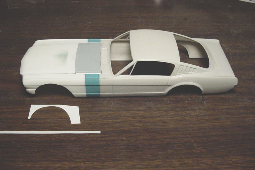 The #2 white stock Mustang hood was glued to the fenders and another light blue stock hood filled in the stretch.
 After adjusting this photo in photoshop to measure out to be the same height and length as the model,
The front wheel well was traced on the photo with frisket film and then transferred to sheet plastic to use a a template.
It became apparent that the SWC Mustang wheel well had been cut 2 & 1/2" above the stock wheel well.
But because were adding a plastic strip (to be used as a wheel well lip), it needs to be cut 3 scale inches.
Adding the plastic strip will bring it back down to 2 & 1/2".
 .020" X .100" plastic strip was used to make the wheel well lip.
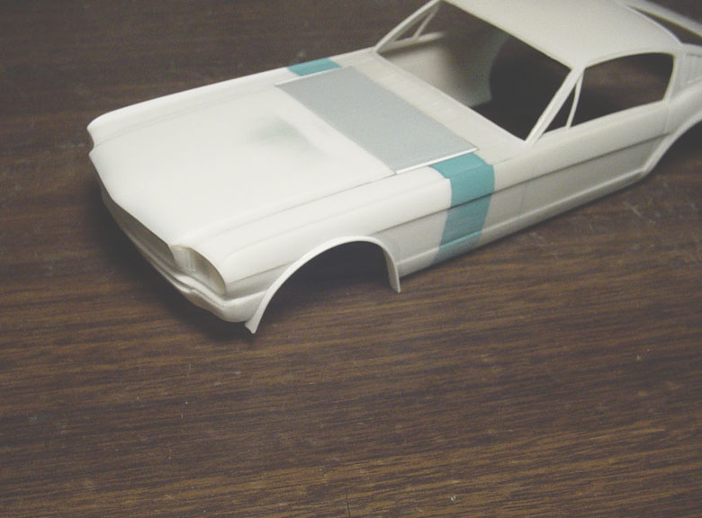
 Before starting the rear wheel well, the back side needed to have plastic strip to fill in the empty space.
 You can see in this photo why the plastic strip was added to the backside of the wheel well,
as it now shows through after removing the inner body recess. The wheel well flares were sanded smooth and
another plastic strip was added to the bottom of the rear wheel well, just as a precaution.
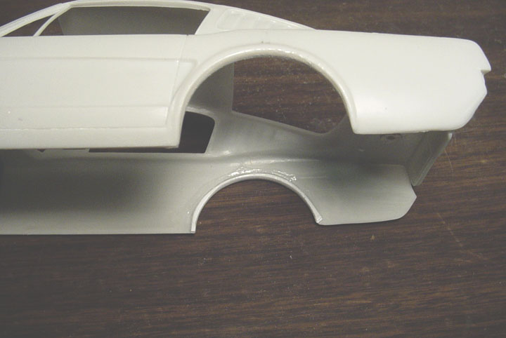
 This photo shows the rear wheel well a little more straight on, so this photo was also measured to fit the body.
Although the body looks bigger than the photo, its just an optical illusion.
You can also see the frisket film traced out to match the body lines for the rear wheel well.
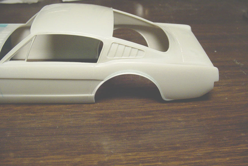 A strip of .020" was added all around the wheel well as a lip, then putty was used to create a wheel well flare.
(note the custom flare tail at the back of the wheel well).
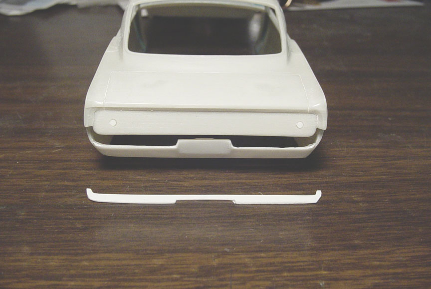 The rear valance had the Tail lights and Licence plate removed and was re-shaped to match the curve of of the quarter panels.
A filler panel was then made, (mainly for casting reasons).
 The 2 vents on the valance were Corvair engine vents (according to a couple of SWC Dark Horse II articles).
The vents were removed from an AMT '69 Corvair. But, the Corvair vents were too long.... (a flaw in the original Corvair model
kit that I noticed when doing the Malcolm Durham Corvair F/C).
So, the 2 vents had to be shortened and a side strip was added to match the other sides.
These vents needed to be counter sunk, So the valance had to be cut perfectly so the vents could be press fitted.
Liquid cement was used to seal them.
 Licence plate mounts and holes were added.
 The articles on the Dark Horse II said it had a Porsche Vent on the trunk lid (no year was given).
After buying a Gunze Sangyo 1/24 Porsche 959 for $20.00 thinking this should work, I Realized it just didn't look right.
I'll scratch-build a better one !
 A parts box grill (like the chrome one above), was a much better choice.
After measuring it all out, A razor saw was used to cut the lines needed to counter sink the 4 dividers using .020" plastic strips.
.020" X .080" were used for the 4 sides.
 Since the vent is aluminum, it really should be a separate piece to make it easier for the build, or it will be a
nightmare trying to mask it off every time you need to paint and clear coat the body.
Here you can see it's almost press fitted into the trunk, but the hole will need to be opened up more due to paint build up.

* Holes were cut in the hood (to fit a 392 Hemi with blower) and trunk (for Porsche style vent).
* New door lines were cheated so the nose can be tilted.
* Semi-hollow door handles were taken from a Ford Thunderbolt.
* Hood was re-shaped to have a crease in the center.
* Weather strip around side windows was made from .040".
* Chrome door molding (on drivers side) was fixed with plastic strip, as it was distorted (a factory error).
* Sail Panels windows were hollowed out.
* New lines were cut on each side of rear quarter panels.
* Grill was filled in with a backing plate.
* HeadLights were filled in (using Taillights from an Ed Roth Mysterion) to create block-outs.
* Front Valance License plate was re-shaped and filler plates were used between the gaps of the Nose & Valance.
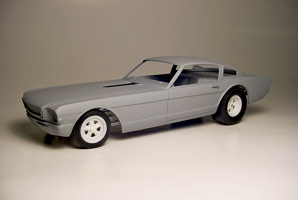
* All body lines were re-sculped and primered.
* Inside of body was thinned.
* Approximately days (and or) nights were spent on filling all sink holes, mold lines & mold imperfections,
Tightening all body lines making them crisp and sharp.
* The body will later be Polished out using a Micro-Mesh Polishing kit for a nice glass finish..... still retaining crisp detail !
INTERIOR TUB
 The original plan was to use a Polar Lights Funny Car chassis as a donor as it looked close to the
real chassis. The Stone, Wood's & Cook Mustang had a 118" wheel base and the P. L. chassis has the same 118" length.
To start the Interior Tub, I needed to know the the distance from the bottom of the chassis (floor pan) to top of the
door panel height. So a Polar Lights chassis was taped together to use as a mock-up chassis using our Speed City
S/S Cragar (zero off-set) Front Mag Wheels and S/S Cragar Rear mags.
Also Speed City Airheart Disk Brakes (with Rotors) from the "Funny Car Parts Pack" was used in place of the P. L. brakes.
The rear end was swapped with a Speed City Resin "Eaton G.M. Rear End".
No matter what mag wheels you plan to use, you will need to do some rear end - mag wheel alteration, as the Polar Lights combo won't work !
 To get a correct ride height, .060" strip was placed on top of the front tires and .080" strip was placed
on top of the Slicks.
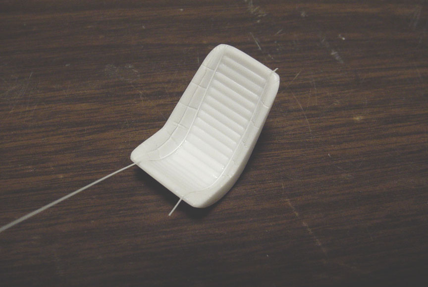
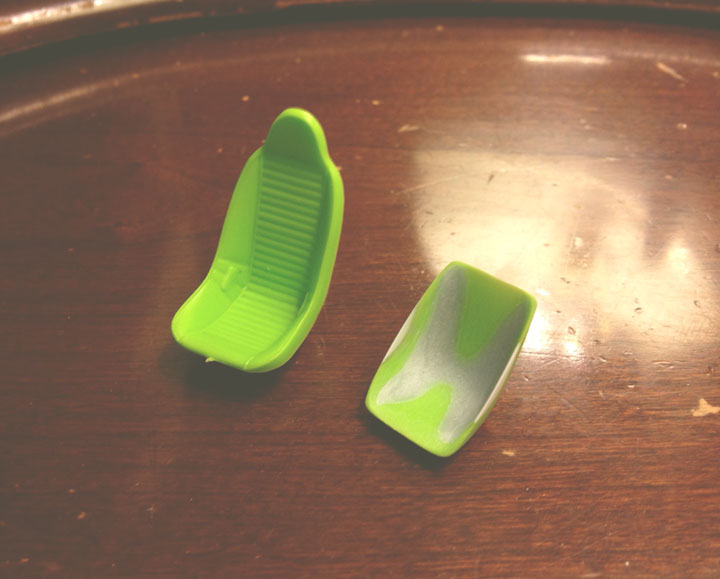
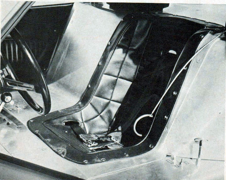 The S.W.C Mustang had the seat counter sunk into the floor pan, so the seat needs to be done first as it will designate how the interior tin will flow.
 Using a seat from the Revell '51 Henry J Gasser (on the left), it needed to be cut down and thinned.
Tuck 'n' Roll pleats were scribed in first with an X-Acto knife, then a dental tool and a jewelers saw and finally the lines
cleaned up with sand paper.
 Piping dividing between the 2 different tucks were made with .010" round tube.
 The seat edges that rolled over onto the interior tin was made from .010" sheet and will need to be shaped to the
contour of the seat.
 An oversight on measuring, I had to remove 2 tuck n rolls from the top of the seat..... (4 scale inches).
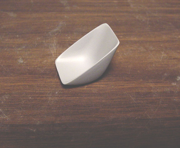
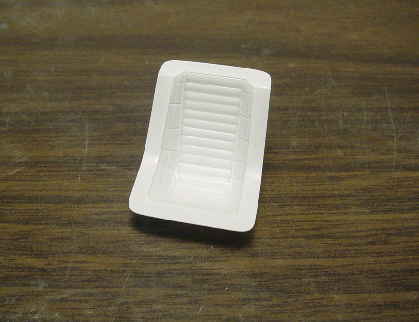 Seat is finished !
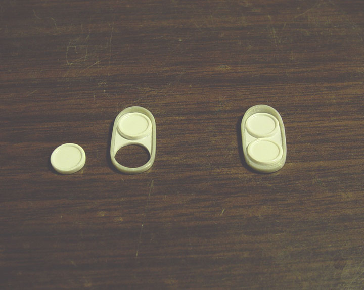
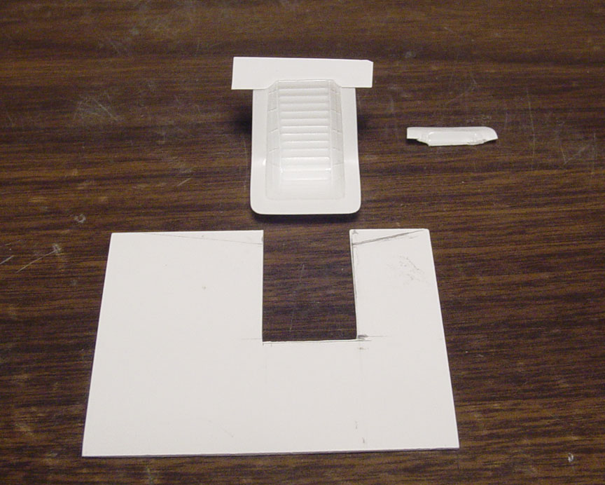
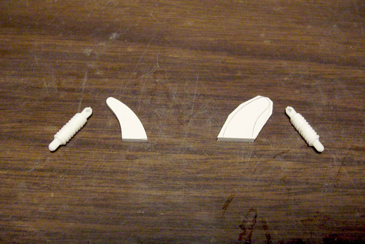
 These are the parts that will create the door panels.......
1. On top..... The door frame
2. Door panel padding
3. Tuck 'N' Roll insert
4. Piping to go around insert & padding
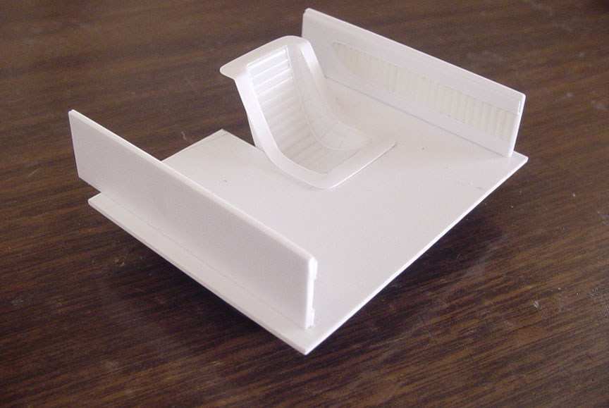 Interior floor with new door panels, measured to fit the P. L. Funny Car Chassis.
 The dash was a bit of a problem, as the the dash on the S.W.C Mustang was flat but curved down at the A-Pillars.
A Dash from an AMT Mustang F/C was re-shaped to better fit the cowl and extensions were put on the sides to keep the new .010" sheet Dash Top straight.
 Too many photos to take of all the progress here, so I'll just explain what all went into making this interior tub.
1. The dash was fitted with a sheet of .010 to keep flat on top and curve down towards the A-Pillars,
but had to be glued with Epoxy, as Super Glue or Liquid Cement would have warped the .010" sheet.
2. The Fire Wall was curved by hand, measured and cut to fit.
3. A Package Tray (or Back Seat Liner) was made from .020" Sheet and glued to the top of the door panels.
4. Side Panels for the seat was made from .020" sheet and matted to fit the seat curvature.
5. Holes for the Roll Bar were drilled using a .100" drill bit (Roll Bar should be made from .080" round tube).....
measurements from the P. L. Chassis were incorporated to make sure these holes will line up to the P. L. Funny Car Chassis.
6. Holes for the Brake Pedal and Shifter Lever were also cut. All holes were back filled using .010" using a punch.
 Bracing around and inside the package tray was made from .060" strip, this will keep it from bowing.
Sheet plastic was also used for extensions on the sides of the interior tub.
Chassis guides were made from .040" strip.
 Two full days were spent on adding 41 Pro-Tech .020" Bolt Heads to the Door Panels and Seat.
The Door Panels were first counter sunk with a round Dremel bit to create a sunken look on the door liner from the buttons.
All the bolt heads (buttons) were sanded and polished to create a round head effect.
Door Handle was Modified from a Lindburg '64 Dodge window crank to resemble the Mustang door handle.
INNER BODY BRACING
 We're just going to call these the "Inner Body Bracing" ?
I've asked around and everyone had a different opinion as to what to call it, but it's the Cowl, Door Jam and A-Pillar Frame.
Many of you will ask, "WHY DON'T WE MAKE THE BODY AND NOSE SEPERATLY AND ADD THESE "INNER BODY BRACINGS" TO THE BODY ?
Here's why- Because this is being made from rubber molds, There is a 98% chance that the 2 pieces will not line up due to fluctuation from the rubber
and you will end up with an ill fitting nose & body. Then you will need to heat
these parts up to fit right.
That's very time consuming and you may end up over heating causing more damage to the body or nose.
We suggest that you scribe out the nose from the body (it's already pre-scribed) with the back side of an X-Acto knife.
That way both parts will be perfectly uniform since they came from the same one-piece body.
 Too many things to describe here, so I'll keep it simple.
These 2 pieces were each built at the same time to make them identical.
100% scratch-built using 24 separate pieces of plastic.
Pro-Tech .020 Bolt Heads were then added to the door hinges.
 To make these fit properly...... Another Mustang body had to be used.
 This is how they will look after the front clip has been cut off.
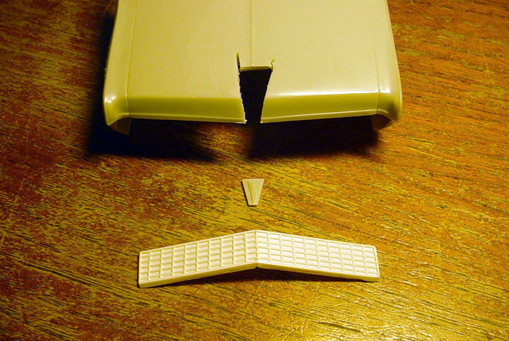
HONEYCOMB GRILL
 The S.W.C Mustang used a honeycomb grill. But, the AMT '66 Mustang has a cross section grill.
A honeycomb photo-etch grill from the Model Car Garage was cut to fit the grill after removing the horizontal & vertical bars
from the original grill insert.
 The biggest problem was how to glue this photo-etched piece down without having glue fill the honeycombs
or having mold rubber creep under it when pouring a rubber mold ?
If that happens, the mold and the master would be ruined (not to mention all the time and materials wasted) !
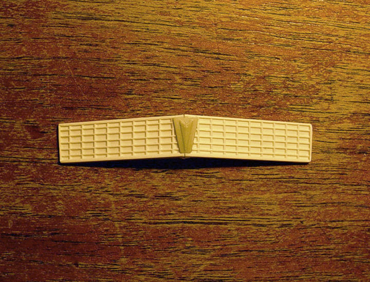
The new photo-etched grill has to be glued down evenly.
After a long deliberation, The best solution was to use my House of Color clear, brush painted on the grill and
dry brushed on the photo-etch piece. Waiting 5 min. to let the clear tack up.
Alligator clips and pieces of plastic were then used to keep photo-etched part laid down flat.
 It worked out great !
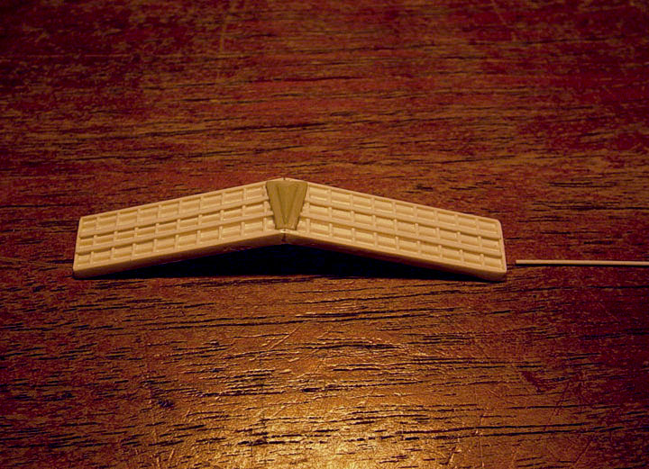
 Master is finished and ready to mold !


Mock up shown using a Polar Lights Charger or Barracuda Funny Car Chassis.
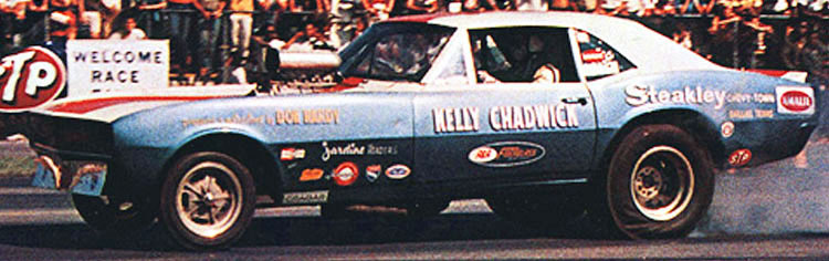
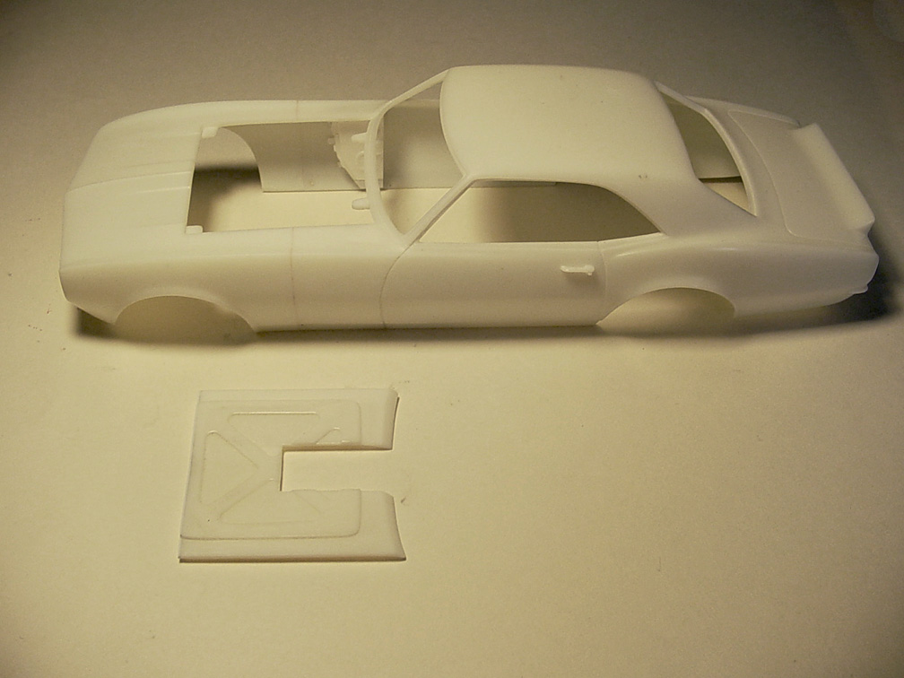
![]()
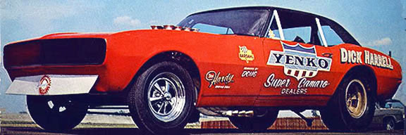
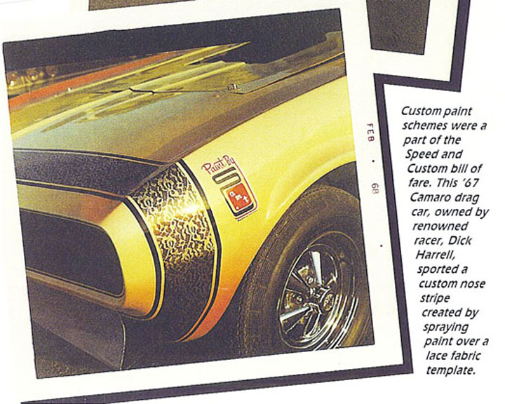
Kelly Chadwick '67 Camaro Funny Car![]() Dick Harrell '67Camaro Funny Car
Dick Harrell '67Camaro Funny Car
Both cars were built by Don Hardy
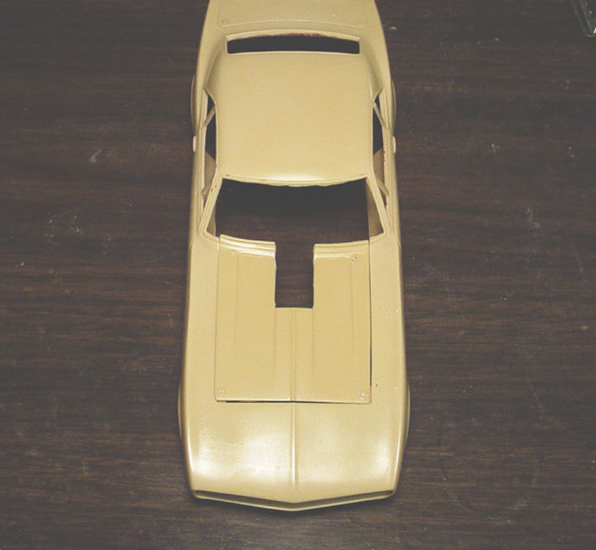
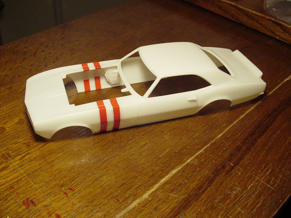
BODY WORK
 This is a quote from Dick Harrell in an article from American Rodding March 1968;
"We moved the rear wheels forward eight inches, extended the front end ten inches and are now sitting on a one hundred and fifteen-inch wheelbase".
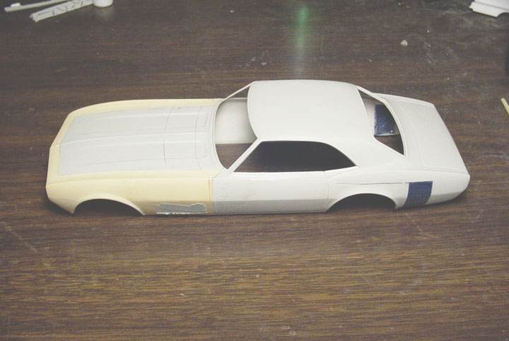
After hours of searching through reference photos and studying the AMT '67 Camaro model kit,
I noticed that the front wheel well was also moved forward 3" (not mentioned in the article).
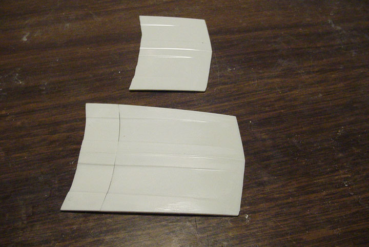
The hood was measured and lengthened from another '67 Camaro hood to make the 15" stretch that the real car had.
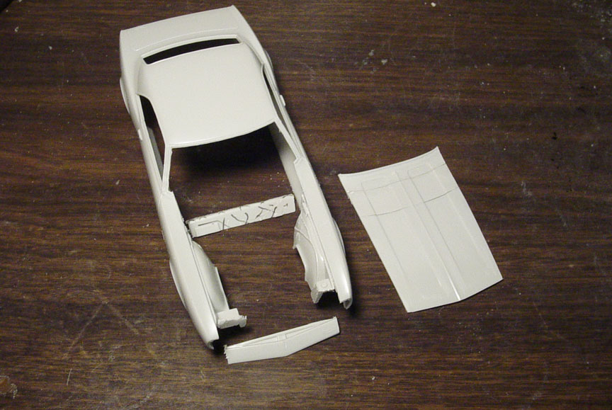 The cowl was cut off and glued to the hood extension (2nd hood). The cowl vents were filled w/ super glue.
The front of the nose and firewall were cut off from a 2nd donor Camaro body to make sure the hood will sit flush.
 We had another unknown resin Camaro body given to us by a friend, but that body had a lot of inaccuracies !
I thought that it would save time from doing a stretch and front wheel well alteration on the other plastic body and to use the resin Camaro body front clip......
A decision I'd later regret !
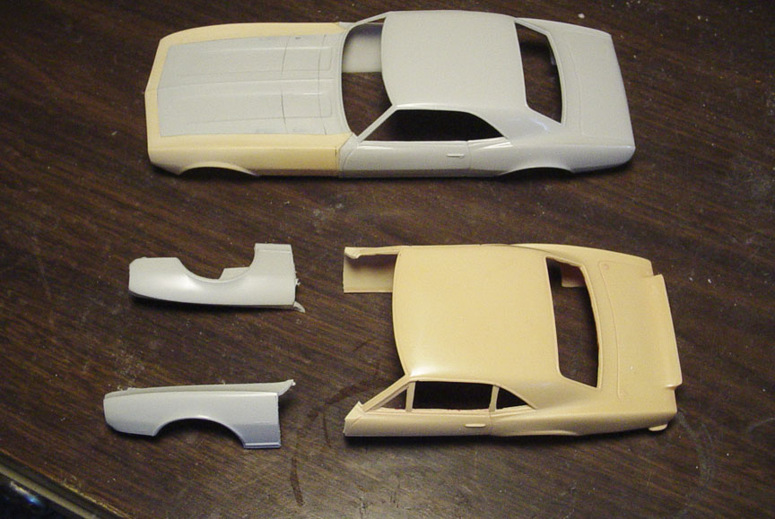
The front Fender, Clip and Nose were removed from the resin body and attached to the plastic Camaro body.
Now the nose will have correct hood molding (unlike the resin body that was void of any moldings)..... shown below.
 Notice the lack of hood detail on the poorly done resin body,
compared to the Dick Harrell Camaro.......When it was re-painted in Candy Gold.
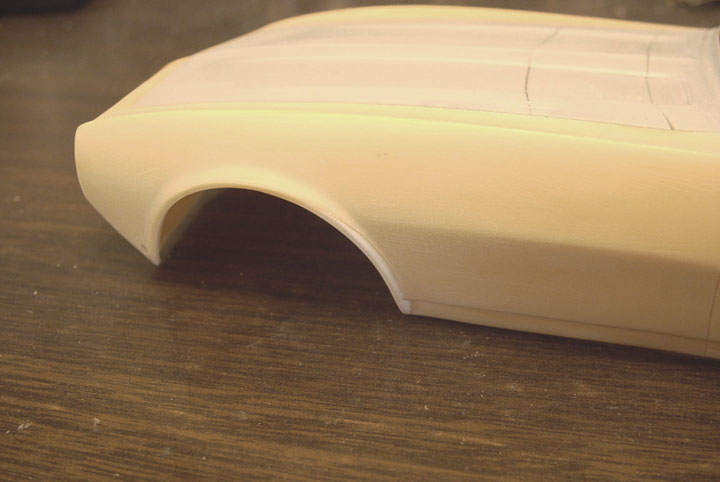 One of the problems on the resin Camaro body were the front wheel well's;
especially the lower wheel lips..... They were sanded off for some reason ?
.080" plastic strips were super glued and the wheel lip and was re-contoured on both sides.
 All trim, wiper blades, scripts, emblems & door handles were removed.
The rear wheel wells were altered and patch panel's were used to fill in the gap from another (blue) AMT Camaro body.
 Here's where I really regret using that resin Camaro body
Not realizing it earlier, but the 1/4 panels on the resin body were sanded flat..... and even concaved in some area's from
over sanding. The top of the 1/4 panels were taped off and putty was used to fill it in.
 The top & bottom of 1/4 panels have been filled and re-shaped to match the original plastic body contour.
With all this work to the 1/4 panels and the front wheel wells, I would have saved time by using the other plastic body
to do the alterations myself. No time was saved by using that resin body !
 A new trunk line had to be scribed into the body before the kit supplied rear spoiler could be added.
The spoiler was shortened 12 scale inches and brought to the edge of the new trunk line.
The amt rear valance was smooth and had no detail, (the real car had a recess below the bumper molding),
so a section of the valance was cut out and sheet plastic was added behind it, to create a recess.
There was no rear bumper on these cars, but rather a bumper molding.
The new bumper molding was made with L-shaped plastic, turned on it's side to make a V-shape.
But since there is now a recess on the valance, we need to add .020" X.060" strip to fill in the hole between the new bumper molding and recess.
(Since every parachute is a different size, the bumper molding will need to be carved out by the builder to match the chute your using).
TO ADD, OR NOT TO ADD, WINDOW RECESS' ???
After talking to some of our customers, I asked if I should add window recess' or keep it simple so customers could
just add stock kit windows from a '67 - '68 Camaro model kit ?
Here's one of the best replies we received.......
"I think you should add the window recess. I believe most people that are buying your products are advanced modelers,
and would have no problem building the correct windows. The attention to detail, and the opportunity to build cars just like
the original are what set your products ahead of the rest". Doug Schultz
 To add the rear window recess, the stock window trim was removed and a sheet of .010"
was fitted to the under side of the window opening.
 Before the front window recess could be added, The hood had to be cut out (for number of reasons).
Accurate measurements were taken to make sure the hood width & length will be correct.
The hood was then taped to the body so the sheet plastic (to make the window recess') would wrap around to fit the
curvature of the cowl.
This time, .020" sheet was used for the front window recess, to add thickness to the bottom edge of the cowl for strength.
 The windows were cut out first with a hot knife, then slowly whittled out with a X-Acto knife and then
sanded to be even all around with a small sanding stick to make all sides of the window recess' uniform.
A strip of .040" X.040" was added to the bottom of the cowl (this will add even more strength to the thin cowl).
Supports for the Hood Pins were added to the correct areas.
(if your adding hood pins, you can pre-drill a hole through the bottom of the supports and hood, then add hood pins
and use small wire or needle for the actual pin).
 In this photo, you can see how nice the hood will fit.
(When adding clear sheet windows; they will need to be cut off right before the hood.
A line is scribed on the cowl, to show you where to cut the bottom of the glass).
 Since the hood is now thinner than the original kit hood, hand cut Hood Structure is being added using
.020" plastic sheet to thicken up the hood, so there will be no warpage problems....... besides that, it adds more realism !
 The hole in the hood was measured using a 427 Rat Motor and a
"Speed City Hilborn Chevy Injection Manifold" for a precise cut.
 The worst part of the original AMT '67 Camaro is the taillights. They look too square and flat.
They're also too small to fit the holes in the body and have no curves to the corners.
.010" plastic sheet was added to all 8 sides and will have to be rounded by hand.
 Notice the taillight bezels are rounded !
 Hard to see in this photo, but the edges are all sanded & polished with a half round shape on the edges.
 Finally, the body was body cleaned up and GM door handles were used from an AMT/Ertl '66 Chevelle SS.
These new door handles are semi-hollow using a divider in between the handle using .010".
This can easily be cut out to make a hollow door handle.
Window Pillars will not be added to this resin body, as they were not pillars, but thin strips of aluminum to hold pexi-glass windows in place.
INTERIOR TUB / CHASSIS
 The Dick Harrell and Kelly Chadwick Camaro funny cars were both built by Don Hardy.
They both had square tube chassis' from the firewall back and round tube chassis' from the firewall forward to the front suspension.
To be make more simple and cost effective for you, we'll start with a Speed City Resin '66 Long Nose Mustang
Funny Car Chassis / Interior tub, since it fit the rear wheel wells, doors and firewall.
All the door panels were removed from the Mustang F/C interior tub and the floor was filled in with putty (from the saw blade)
to make smooth again. New door and trunk panels were made from .040" plastic sheet to match the curve of the top of the doors and trunk on the body.
 Unlike the Mustang funny car which uses leaf springs, the Camaro uses a coil over rear suspension.
So, the bottom of the new Camaro chassis needs to have a frame for the coil overs and shocks to mount to.
Plastic strips were used to make a frame between the main frame rails. And .040" strips were added for extra support rails.
 After studying the inner door frames on both the real cars, the holes were drawn out with pencil
and templates were cut out on .020" plastic sheet.
 The top of the door frames have arm rest moldings that are the same color as the body.
To make this, .020" sheet plastic was added to the top of the door frames.
(These will be re-shaped later to resemble the real car's door panels).
 Tub was fitted with a dash and putty was used to form the contour that the aluminum sheet metal had.
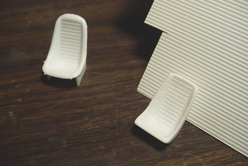
 Both cars had the same fiberglass bucket seat shell (shown here).
After sifting through all the seats and model kits in my inventory and asking around, it was determined that no such seat
was ever made in kit form.
We want you to be able to build an accurate model, so were going to scratch-build a correct seat.
 After sifting through a parts box of seats, a good starting point was to use the seat from the Revell Malibu Pro Street "MAX RAT".
The seat sides were all cut down, sanded smooth and plastic strips were added to the sides of the seat (for a correct angle).
Putty was then used to round the inside of the seat.
 The finished " Fiberglass Bucket Seat Shell" master.
 Another part that was never offered in kit form is a B&M Shifter Box.
To build an accurate rendition of these Camaro Funny Cars, we'll need to scratch build one.
Here it is....... This part may be offered separately later ?
FRONT SUSPENSION
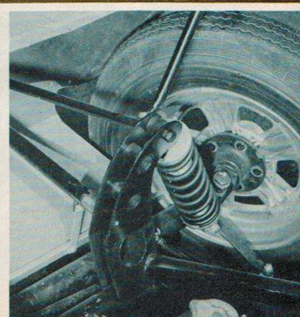 The front suspension on the Dick Harrell & Kelly Chadwick Camaro's are Coil Over Shocks mounted to tall shock towers.
After checking all other Funny Car front suspension parts, I came to the conclusion that the shock mounts
on the real cars are taller than any of the other AMT / MPC / JOHAN / POLOR LIGHTS / model funny car suspension's.
 Measuring from the bottom of our new Interior Tub, (where the round tube chassis will be attached)
and figuring the length of the shock, new Shock Towers were drawn on .080" plastic sheet, cut and shaped by hand.
 The new Shock Towers are mounted to .010" sheet. (This was done for casting purposes).
The holes can easily be drilled out.
 Coil over shocks were added mainly to be able to set the ride height.
(Round tubes don't cast well with rubber molds and they tend to be off center).
These coil over's may not turn out perfect. but these can be removed and nicer aftermarket shocks can be added by the builder.
But these will work for doing your mock up.
 Extension's of the square tube frame was added to the firewall and will have .080" holes
drilled in them
Extension's of the square tube frame was added to the firewall and will have .080" holes
drilled in them
for the round tube frame rails to fit into.
MOTOR MOUNT
 Thinking how hard it will be to make motor mounts to set the engine height on the model build,
especially on a round tube chassis (which this car had). I figured we already have a BBC Timing Chain Cover from the
"M/T BBC Parts Pack", so why not use it and make a new motor mount plate out of sheet plastic.
After careful planning of where the engine needs to be, .020" sheet was used and lightening holes were drilled in it.
Another .020" sheet will be glued to the back side to fill the Lightening Holes (this was done for casting reasons),
so you will need to re-drill the Lightening Holes...... if you want them hollow ?
 Although our motor mount isn't 100% accurate as the real car is (shown in this photo), this motor mount will be
an easy task to install your choice of a 427 Chevy Engine.
MASTER IS FINISHED !

UPDATE:
Unfortunately, I was misinformed about the quote from Dick Harrell in the article from American Rodding March 1968;
"We moved the rear wheels forward eight inches, extended the front end ten inches and are now sitting on a one hundred and fifteen-inch wheelbase" is incorrect !
The body always seemed to long to me and I even asked a friend to look it over before putting this model into production.
He said that maybe it's just an optical illusion?
I went back to review all the measurements and found out that after doing the wheelbase alterations according to the article;
The wheelbase would not be 115", it would be 110". And, if I also include the 3" front wheel moved forward, the wheel base would be 113" !
To make our body correct 5 scale inches (5 m.m.) would need to be removed from the hood and fender panels.
Sadly, this model was such a poor seller, that I don't know if I'll ever fix the master and put it back into production?
After years of being a master model builder for Speed City Resin, I have realized to not trust magazine articles !
To make your resin body accurate; contact me at; skmodeler@sbcglobal.net
For instructions on body & hood alteration.

After searching all plastic kit Daisy mags and aftermarket companies for years
to find a good representation of a correct DAISY mag wheel, I have come to the conclusion that none was ever made.
Although we currently sell a Daisy 15" mag wheel, it just doesn't look right.
We will be discontinuing that mag wheel, so that we can give you an accurate 16" Daisy Drag Mag !
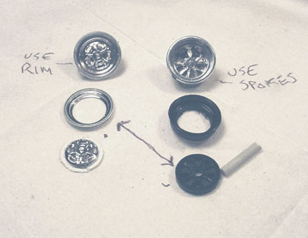
 I'll try to make this sound as simple as I can, but be live me, it was a painful event !
After spending 2 days contemplating on how to make a 15" Daisy mag into a 16"mag with larger spokes.
I Started with a Daisy 15" "street machine" mag wheel.
The top of the rim was sanded down almost to the spokes. The back side was also sanded down.
Putty filled in the low spots on the face of the spokes and was hand sanded to make even on all 5 spokes.
The center cap was also lowered to be even with the spokes.
 A rare Johan 16" Funny Car inner rim will be used for a new outer rim.
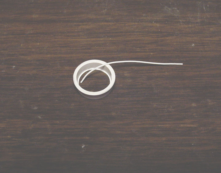
.020 plastic strip is used for a lip (just before the spokes).
 The Daisy "street machine" mag doesn't have a center cap mounting plate, like the real one has,
so the center cap mounting plate needs to be cut from another mag wheel ( shown in chrome).
 The new Daisy mag needs a backing ring, to do this, the mag was glued with liquid cement to a .030 sheet.

 Pilot holes were drilled with a dremel.
A parts box small rim was lightly glued to the back so the that the backing ring would be straight. (not shown in a photo)
 To make sure that this new Daisy mag will fit a Polar Lights suspension, a parts box mag wheel post was cut
and glued to the center. Another 3/32" hollow round tube was inserted into the post, so that a metal axle can be used for different suspensions.
 10 - Pro-Tech .020" "Nut & Bolt Heads" were glued to the backing ring.
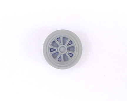
 Master is finished !
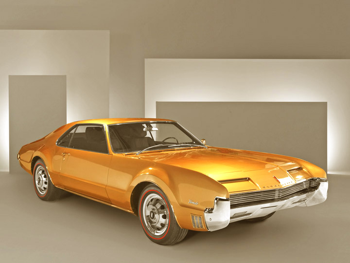
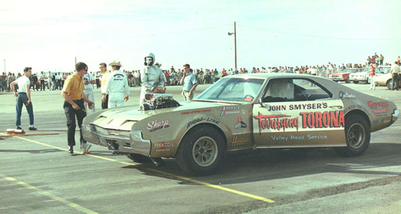
Our
original intent was to make the "Terrifying Toronado" drag car
only, but we know the stock builders would only want
the stock version which would need to come with parts that wouldn't be necessary
for the drag version.
It was very confusing to figure it all out . Anyway , here's what we propose.........
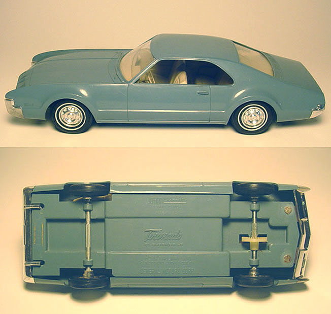 An original Johan 1966
Olds Toronado Friction Promotional Model Car will be used for this project.
An original Johan 1966
Olds Toronado Friction Promotional Model Car will be used for this project.
Since this '66 Toronado will be used for both stock & drag versions,
we'll need to figure out which parts to use that the other version wont
use ?.........
in other words if your buying the "Drag version"
you wont end up with "stock version" parts you will never use
(such as hub caps, etc.)
Footnote: The 1966 Toronado
was offered by Johan as a 1/25 model kit.
It has never been re-issued and is a very rare model.
It took 3-1/2 years to acquire the friction promo you see here.
BODY
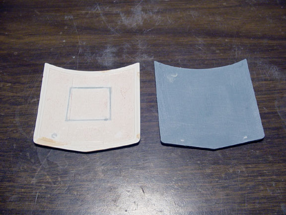 The original hood was cut out and removed from the body.
The plan is to use a '67 Toronado hood from a different mpc kit since it
has nice underside detail (hard to see in the photo).
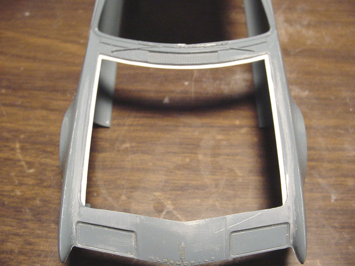 Using the white hood as a thickness guide between hood and sides, new hood
supports were installed using plastic strip.
Using the white hood as a thickness guide between hood and sides, new hood
supports were installed using plastic strip.
The new hood will fit perfect !
 Here's the new mpc hood
on the Johan body.
Here's the new mpc hood
on the Johan body.
 All holes were filled on the rear valance.
STOCK VERSION
 The Promo hubcaps had to be altered, so they can be used on the '66 Olds 442 (donor kit).
The thick axles were removed and the rims cut off. They were all sanded
to be as thin as scale hubcaps.
 The firewall was filled and the rear portion of the packege tray was filled with plastic strip for a better fit.
 The taillights were added to the rear bumper, this makes it easier to cast and all you'll need to do is
chrome plate it, Allclad it or (MOLOTOW Chrome Ink is now available) and paint the taillights with some red clear paint.

![]() The MPC '67 Toronado kit has a great 6- piece Trans Axle, but that's too many pieces to cast to make it cost effective.
The MPC '67 Toronado kit has a great 6- piece Trans Axle, but that's too many pieces to cast to make it cost effective.
So, we glued them all together and will cast this new Trans Axle as a single item.
 Here's all the parts that will come with the "Stock Version".
DRAG VERSION

 The Terrifying Toronado kept the rear seat,
so we're adding a stock interior tub to the drag version......The tub will need to be altered a little.
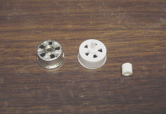
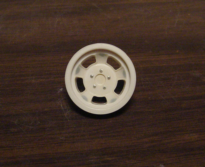
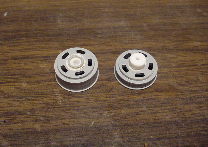
 After an extensive search, we could not find exact wheels to match those on the real car.
 So we had to hand craft them.... Here's a photo with description on how it was done.
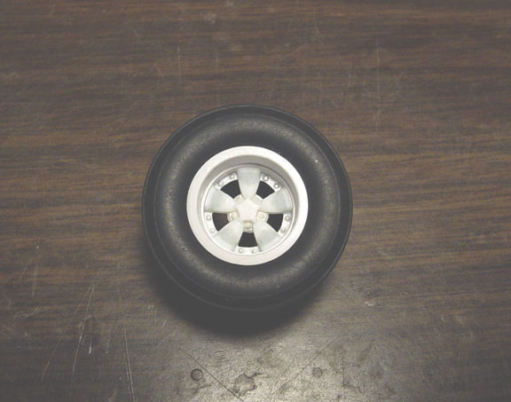
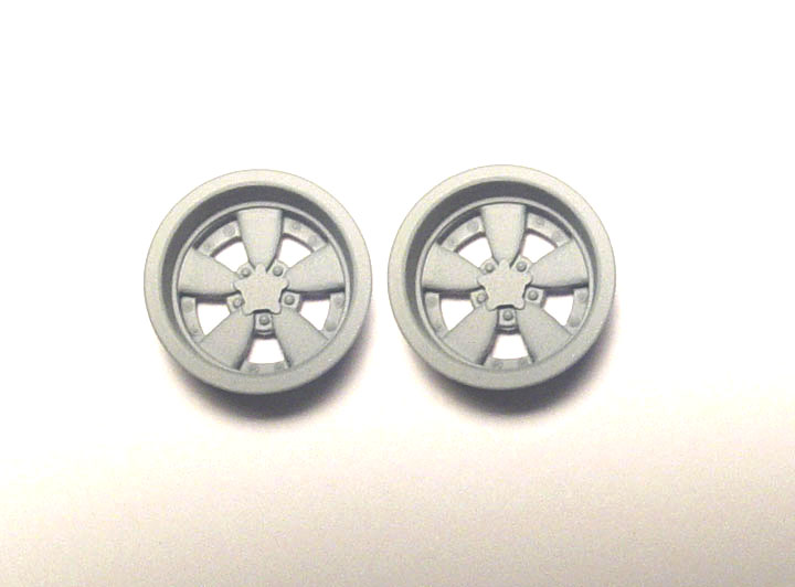
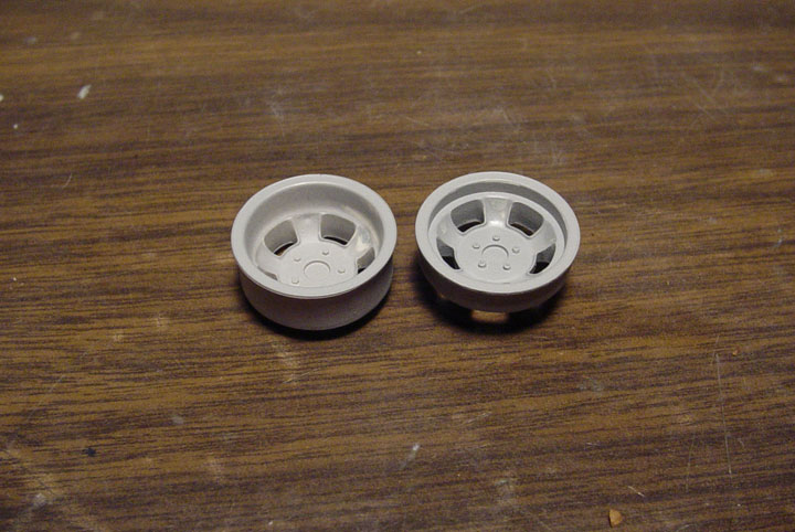
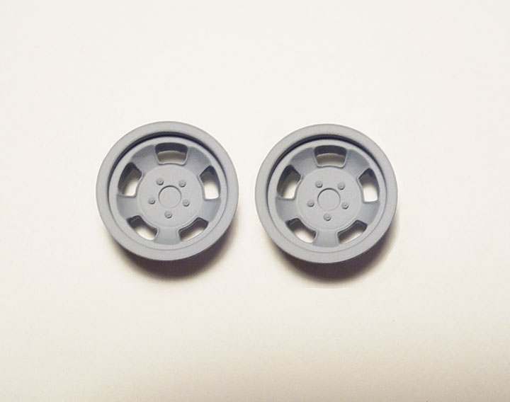
 A new "HALIBRAND INDY 500 SPEED WHEEL" master.
This mag wheel will be cast and 3 other castings will make up the 4 wheels needed for this project.
 Here's all the parts that will come with the "Drag Version".
We will include 2 - sets of Enderle Bug Catchers and the stock interior tub and dash.
The interior tub will need to be re-worked for the Terrifying Toronado, but at least its there !
You'll need a Monogram Hurst Hairy Oldsmobile for a donor kit.
Not satisfied with any of the kit Enderle Bug Catchers, we set out to make an correct one !
Although "Blower Hat" is the correct term, I decided to call it by it's nick name "Bug Catcher".
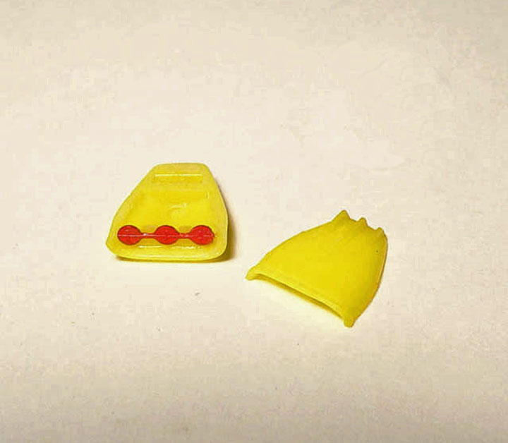 Starting with an MPC Funny Car Blower Hat, a Revell "Butterfly Set" was added and finished with a
.0.10" plastic round tube for a throttle Rod. I then added .040" rods on each end to resemble the Throttle Rod ends.
MASTER IS FINISHED
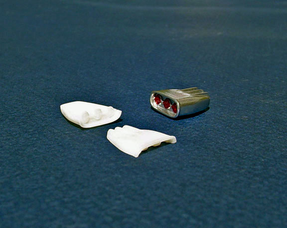
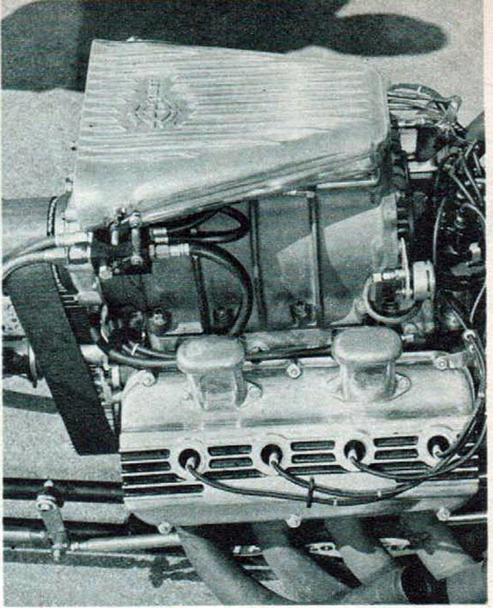
This MPC Crower Bug Catcher kit part has no detail and has gaps on each of the butterfly holes.
I'll be changing this too !!!
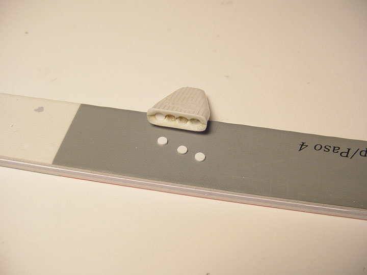 Starting with an MPC Crower Blower Hat, I filled the gaps between each hole with super glue gel and
sanded to perfection. 3 - round "Butterflies were made from .020" sheet punched out and the edges cleaned up.
 Putty was added to the holes on each side and .010" Rod was glued across each of the 4 butterflies for the Throttle Rod.
.040" rod was cut to resemble the throttle rod ends on each side of the Hat. An "Injector Base" was scratch built from plasdtic sheet.
MASTER IS FINISHED

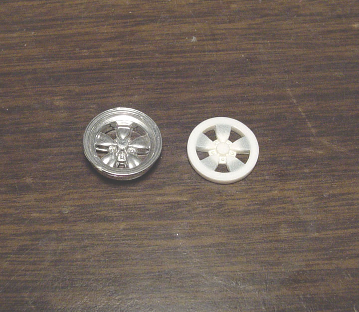
None of the model kit manufactures got these right.
If you look at your model kit that are supposed to have Halibrand rear mags, you'll see that they are incorrect.
These new mag wheels will be period correct for 60's style Gasser's, Altered's, Dragster's and Funny Cars.
 Starting with an original Johan (deep dish) mag wheel from the original '64 Plymouth Funny Car kit.
The chrome was stripped, the wheel was cut in half, re-sized and re-glued.
Five new photo etched (Nuts & Bolts) were added.
 All the ends of the spokes had sink holes due to the original plastic injection molding cooling too fast.
These were filled, sanded and polished.
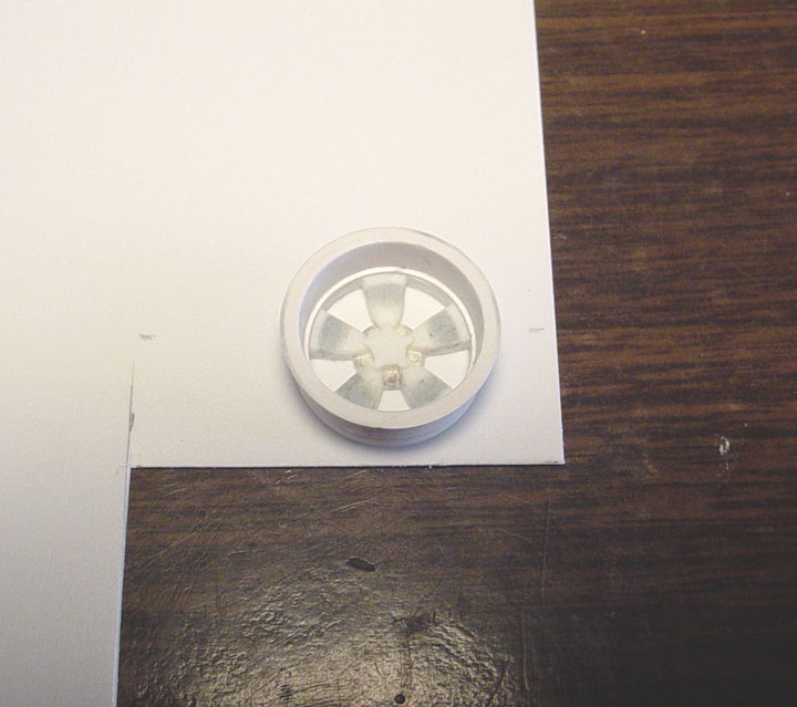
 To be able to use these new Halibrand Rear Mag Wheels on the Polar Lights F/C rear suspension,
we needed to extend the hubs, otherwise the slicks would go back too far and hit the chassis.... among other problems.
 Now the shallow dish mag wheel (on the right) is the same height as the deep dish..... and so is the hub.
The spokes were also cleaned up.
 Masters are finished.
It would have been so much easier to do this in 1/24 scale, as those Jaguar kits are more
available,
but we really wanted this to be in 1/25 scale if possible !
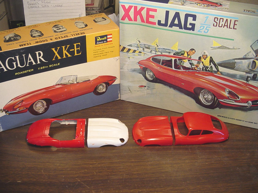 This photo shows the original
1/25 Revell Jaguar convertible kit and the "Aurora 1/25 Jaguar Hardtop"
reissued by (Revell-Monogram) in 1998.
This photo shows the original
1/25 Revell Jaguar convertible kit and the "Aurora 1/25 Jaguar Hardtop"
reissued by (Revell-Monogram) in 1998.
The Aurora hardtop body looks great, but the nose doesn't look half as good
as the Revell Jaguar convertible's.
So, the plan is....... to mesh the
Aurora Body with the Revell nose,
to create the most accurate Jaguar hardtop
Funny Car body in 1/25 scale.
 We removed the B-pillars, door handles & windshield wipers, filled the bumper
holes,
We removed the B-pillars, door handles & windshield wipers, filled the bumper
holes,
cut out some of the Rear valance and went over the Aurora hardtop body
with 320 grit sandpaper.
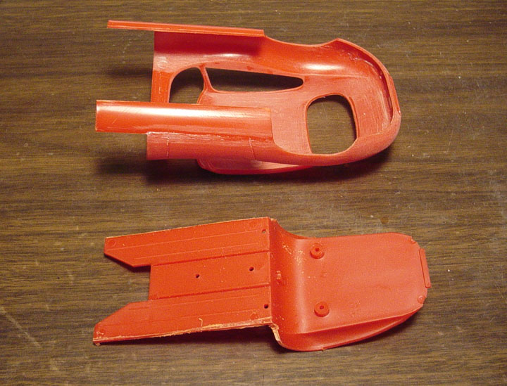 The rocker panels were cut from the chassis and glued to the body.
We will be
removing an 1/8 of an inch from the bottom of the rocker panels.
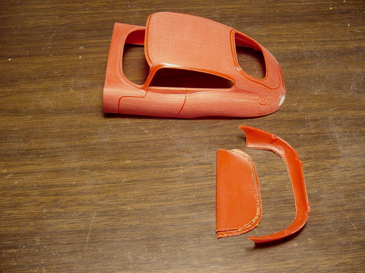
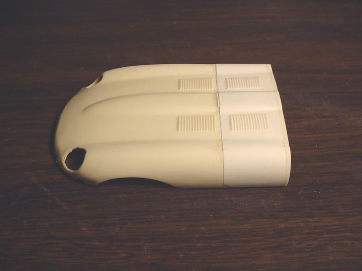 We got the extra nose clip
from Aaron Dupont, and here it is molded to the stock nose.
We got the extra nose clip
from Aaron Dupont, and here it is molded to the stock nose.
2 scale inches were cut from the stock nose,because we need extra room for sanding,
we then added 2" to the rear of the nose,
to make up for removing the previous cut. The nose has been stretched 20", just as the real car was !
 The Head light bezels were installed and sanded to the fenders.
Head light block outs were carefully installed with a slight lip. Here's the nose all puttied
& Sanded.
 The Rocker Panels were too
short to match the new Nose. So,
The Rocker Panels were too
short to match the new Nose. So,
I removed them, this also helped when gluing
the 2 body pieces together.
 Cutting the Rocker Panels from the Revell Chassis' we glued both together to
get some added length.
Cutting the Rocker Panels from the Revell Chassis' we glued both together to
get some added length.
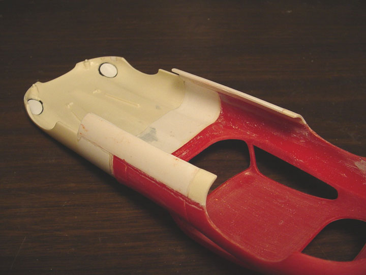
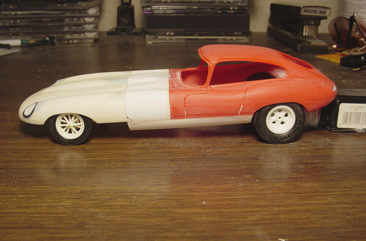 New Rocker Panels !
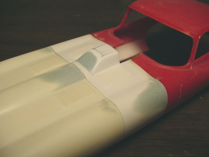 Finally, the "hood scoop"
!
Finally, the "hood scoop"
!
 We filled all the bumper holes on the Valance, and filled the grill area with
a block out.
We filled all the bumper holes on the Valance, and filled the grill area with
a block out.
 The first shot of the body in primer. It still needs some minor puttying and
sanding.
The first shot of the body in primer. It still needs some minor puttying and
sanding.
CHASSIS
These photos and instructions will show how to make your model of the Snoopy F/C
using a Model King "Kenz & Leslie Cougar" F/C for a donor kit.
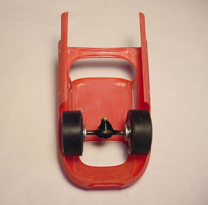 While waiting for an extra nose piece, we decided to start on the interior tub.
But, before we can do an Interior Tub, we needed to make a mock up chassis.
First, you'll need to shorten the Cougar F/C kit rear axle's,
so the slicks you use will fit the inside of the body.
INTERIOR TUB / FIREWALL
 This article shows
the Snoopy Jaguar chassis & Interior tub.
This article shows
the Snoopy Jaguar chassis & Interior tub.
Although our Interior tub & Chassis wont be 100% accurate,
it will be close enough to do a decent build !
 Starting with an old
mpc floor pan, and the trunk section from the Aurora Jaguar,
Starting with an old
mpc floor pan, and the trunk section from the Aurora Jaguar,
we'll be creating a new Interior / Firewall !
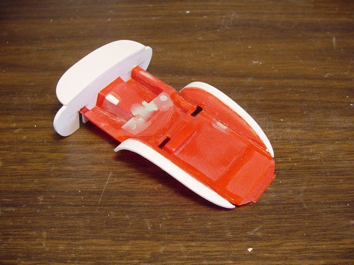 We started by cutting off
the front of the mpc floor pan, out about 8", the Aurora firewall was traced out,
We started by cutting off
the front of the mpc floor pan, out about 8", the Aurora firewall was traced out,
then we added a new cowl. The Fender wells from the Aurora Jag were cut from the original and glued to the mpc floor pan.
Extra plastic sheet was used
to widen the fender wells, then the rear section of the Aurora floor was added
to the rear of the mpc floor pan,
so it can hold up the the body...... ( it sounds as confusing as it was to build ! )
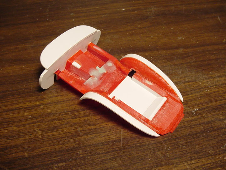 The floor for the drivers seat needed to be lowered,
so we went back to cut
it out and lowered it 6" using plastic strip & sheet.
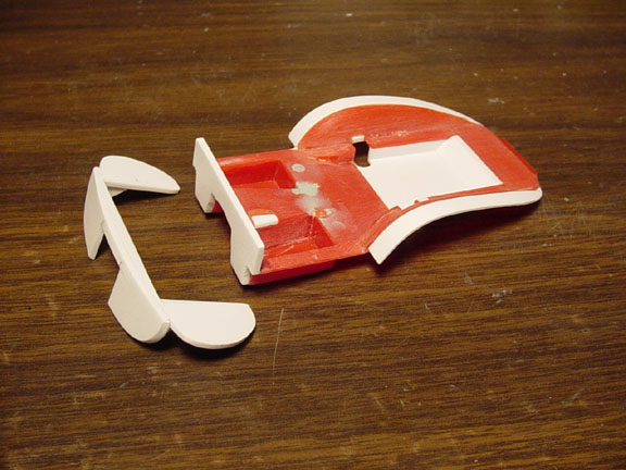 The Firewall & Cowl was
carefully cut from the Interior Tub.
The Firewall & Cowl was
carefully cut from the Interior Tub.
 Here's the finished Interior
Tub & Firewall & Cowl.
Here's the finished Interior
Tub & Firewall & Cowl.
BACK TO THE BODY
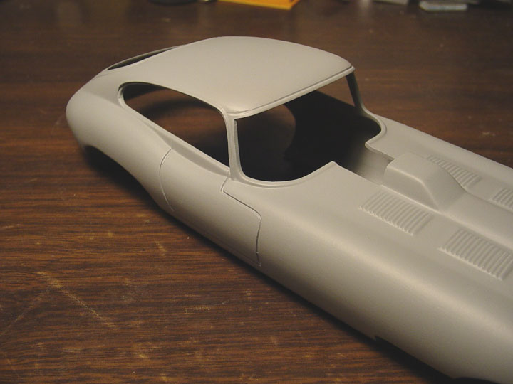 The top of the original
Aurora windshield trim was too curved, so we puttied in the old lines,
The top of the original
Aurora windshield trim was too curved, so we puttied in the old lines,
and re-scribed new squared lines, this gives it a more aggressive look.
 lastly, we added the Speed Holes to the Trunk Door & Body.
Initially, the door was going to be a separate piece, but after reviewing,
I see problems occurring with the door edges warping, due to the top & sides
of the door are too thin.
You would still need to make door hinges, and for those who don't want to spend the time, would glue it shut any way.
The door can be scribed out with an E-xacto blade, if you wish to make it swing
open !
FRONT SUSPENSION
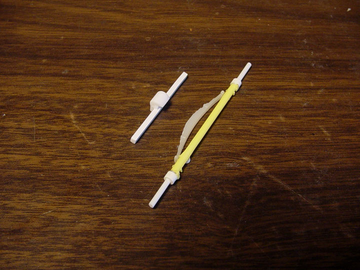 The front suspension on the Kenz & Leslie Cougar F/C, didn't work for a number of reasons,
so were going back to create a new Front Frame with a Spring Perch, and a Correct Tube Axle with Buggy Spring.
Starting with an mpc Front axle, we cut off the shock supports and cut the axle
back 8 scale inches on each side.
New hollow tubes were glued to the axle, and
then we added new plastic tubes inside the hollow tubes for new spindles.
The Spring came from a Revell Model A Pickup Truck axle, we cut the spring from
that axle and re-glued it to the mpc axle.
Because the spring sticks out too far, the Sway Bar will need to installed behind
the axle,
so a small tube was added behind the tube axle as a mounting hole.
The Spring Perch
came from the Monogram Ford T Roadster, it was mounted to a square tube (to be used as a front frame rail).
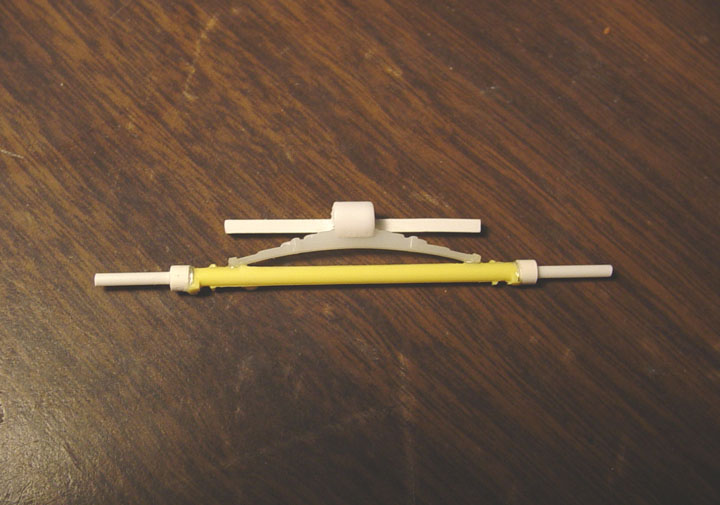 This is how the 2-pieces will look when attached to your model.
MASTER MODEL IS FINISHED
We are including
a set of American 12 Spoke Mag Wheels and vintage mpc Funny Car Cragar Mag Wheels !

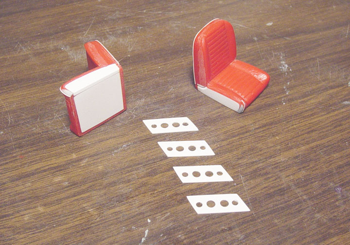 Starting with the correct A-100 seats from the Lindburg "Little Red Wagon";The sides and bottoms were filled in with sheet plastic.
The left and right side of each seat had to be reshaped with putty as they were uneven (to fit the engine cover on the L.R.W.).
Then the seat piping was added using 0.10 plastic rod around the back and sides of the seat.
Here you can see the seat brackets being made from sheet plastic starting with drilling different size holes and angling the sides.
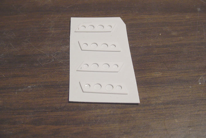 The brackets were then glued to a piece of 0.10 plastic sheet, this is needed to be done for casting purposes,
which can easily be hollowed out by the builder.
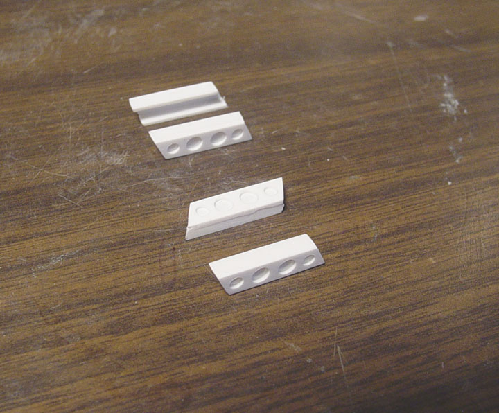 Tops and sides were added for gluing to the bottom of the seat and the the floor boards.
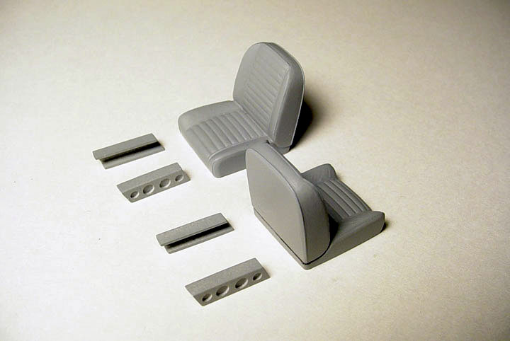 Here you can see the new piping along the sides of the seat and the lines cut to resemble a 2-piece seat.
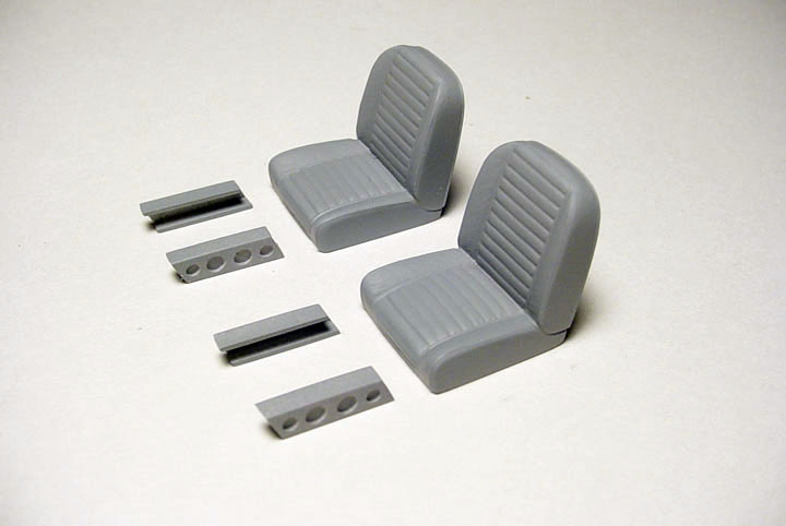
The master is complete !
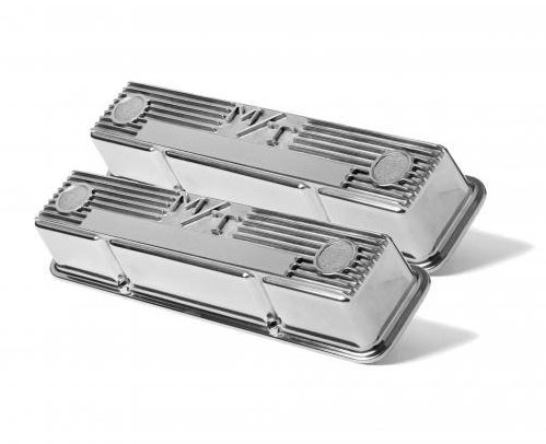
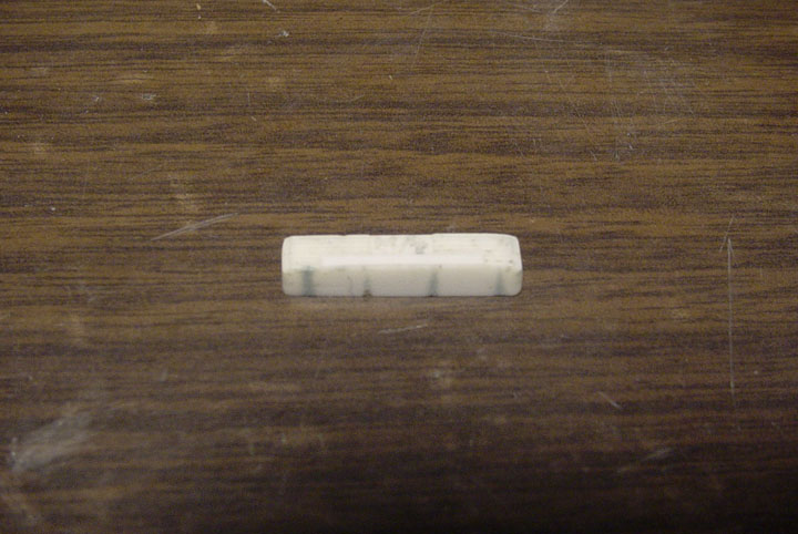 Although this is a really bad photo, it started as an unknown resin cast M/T Chevy "Big Block" Valve Cover.
Unfortunately, the casting has pin holes that will need to be fixed.
All the grooves for the bolt heads were filled in with putty and the bottom lip was removed.
This was done because it needs to have only 2 bolt heads per side and to be a bit smaller in length and width to fit a small block Chevy motor.
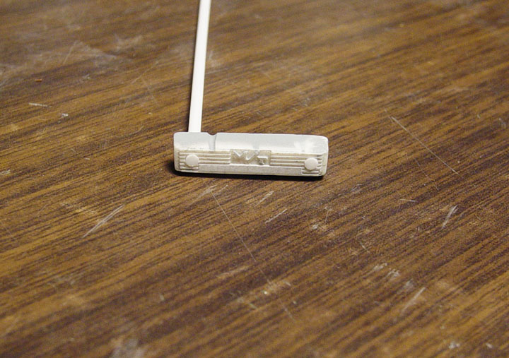 The oil filler plugs were made by drilling holes on each side of the cover and then filling the holes with plastic tubes flush with the top of the fins.
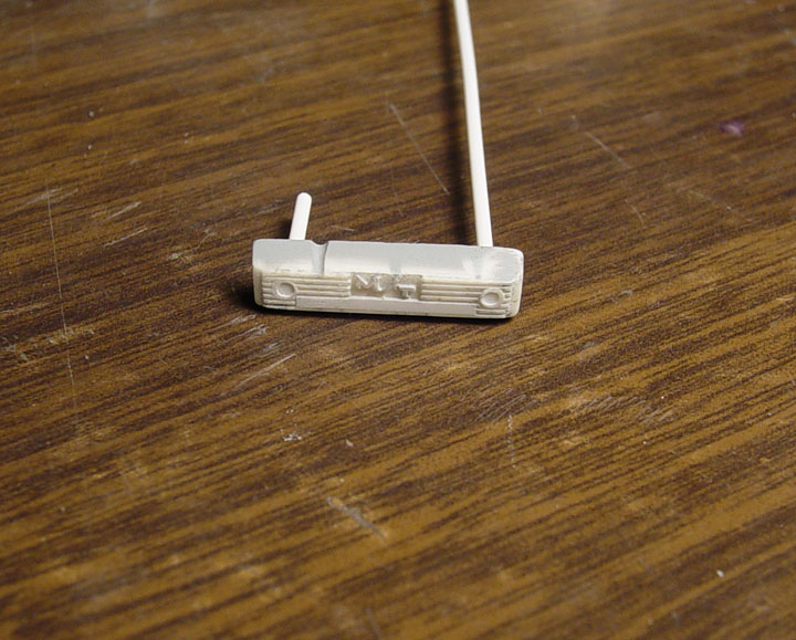 The tube was then drilled out and filled with another smaller plastic tube slightly lower making nice filler plugs.
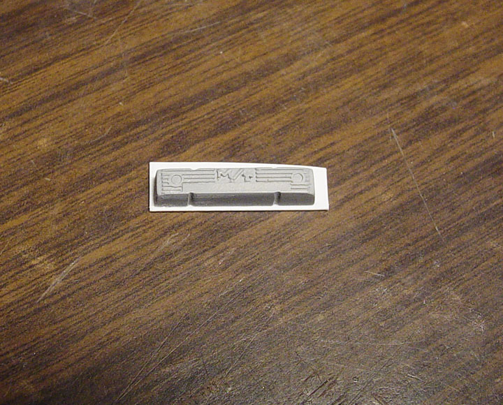 Plastic sheet was used to form the lip.
Its looks pretty rough at this point as you can see, there are tiny pin holes and a chunk of resin under the M/T logo.
 The lip was reshaped and Small plastic rod was cut to resemble bolt heads. but you can see there is a lot of clean up to do on this part !
A lot of filling tiny pin holes, cleaning up the fins, sanding and trying to make perfect.
We have a great looking piece !
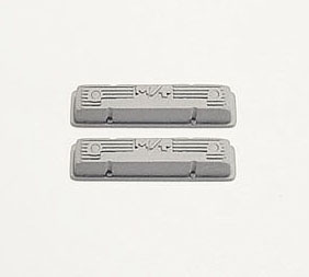
The master is complete !
![]()
All rights reserved. Do not copy any Speed City Resin bodies or parts without permission and consent.
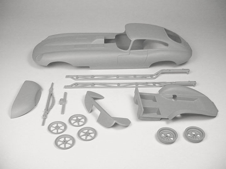
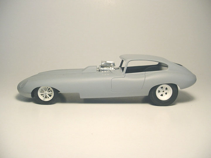
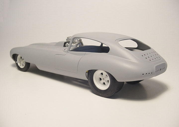
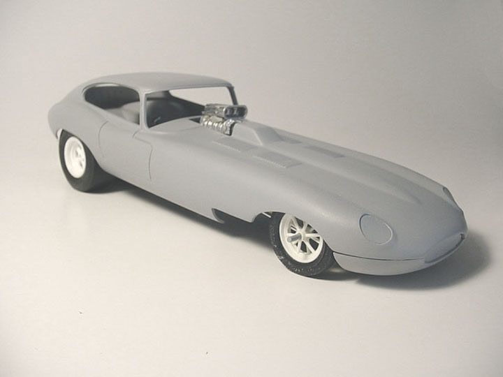