"IN PROGRESS"
On these pages you'll see how we create our master models and parts,
so you can see the labor of love that goes into all our products.
You won't find any sink holes, mold lines, waves, dips or any other imperfections
that are found on every plastic model body.
After all modifications and alterations, The bodies are wet sanded & polished, so no imperfections are left.
Because of that..... Yes, our resin bodies are better than plastic kit models !
As with all resin parts, you will need to clean up some flashing around each resin part.
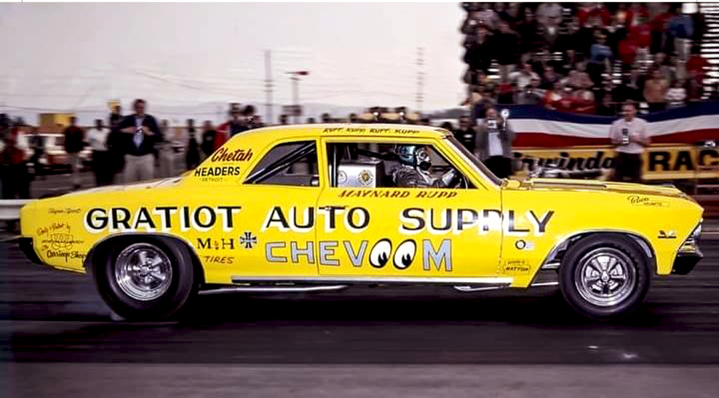
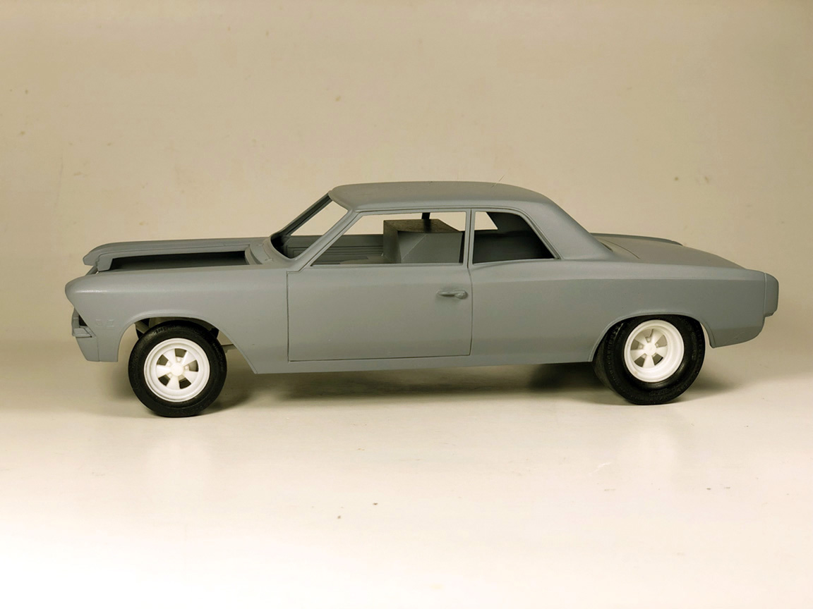
This car gets a little confusing as the body shows that it's a 1966 Chevelle 300 Deluxe Sedan Post body.
but it also has the Super Sport (S/S) Trim, Hood, Grill, Trunk Panel & Rocker Panel Trim.
According to an article in Popular Hot Rodding May 1966;
"A Chevelle body was borrowed from Shalla Chevrolet Auto in Detroit Michigan and a fiberglass body was reproduced from it".
Although not mentioned in the article, they must have added all the Super Sport replacement parts to create an all new model?
Drag cars from the 60's certainly were unique to say the least !
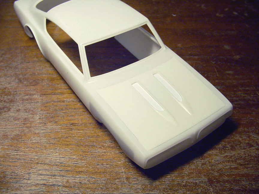
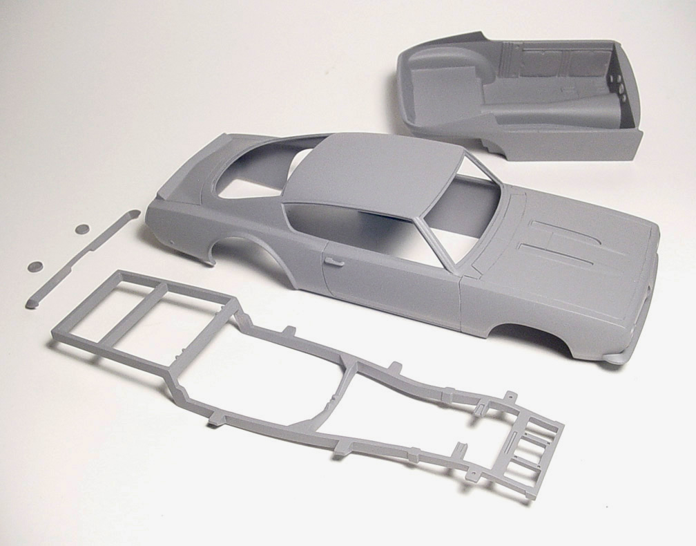
BODY
 Starting with a Lindburg 1966 Chevelle Super Sport for the body and a Revell '65 Chevelle Malibu for the Sedan Roof;
I destroyed the roof on the '66 Chevelle SS (to save the pillars on the body) and destroyed the pillars on the '65 Malibu (to save the roof).
 The '65 Malibu Sedan Roof was then grafted to the '66 Chevelle SS body. I'm also planning ahead for the B-Pillars.
So I carved a space between the door for the upcoming B-Pillars.

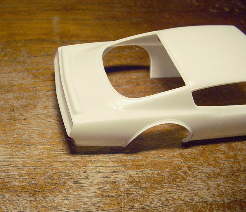
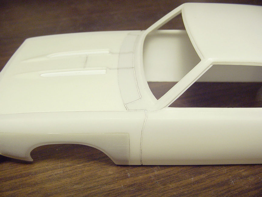
 The rear window on the '65 Malibu Sedan Roof needed to have 3 scale inches removed from the top frame to be higher.
 After clean up, new window trim was scribed in.

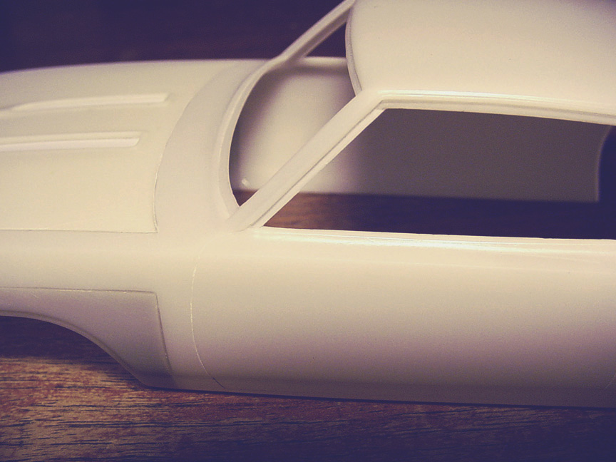
 The top of the sail panel needed to be rounded off, so plastic strip was installed on both side of the sail panel.

 New drip rail was shaped from the plastic strip & super glue and the B-Pillar (made from different strips of plastic),
was instead on the correct angle.
 Since the original Chevoom didn't have rear window trim, I decided to make the rear window recessed.
 Now on to the rear wheel alteration. The article states that the wheel base was 129" on the Chevoom Chevelle Funny Car.
The stock wheelbase for a '66 Chevelle is 115". So the alteration needs to be a 14" stretch- (rearwards).
Magazine articles have been wrong before; so I double checked with measurements and 14" is correct !
After careful planning; I cut the wheel wells out on the master body just before the front rear wheel lip,
and made patch panels from a second '66 Chevelle SS with 14" added before the rear wheel lip.
This will also help with lining up the 2 panels so there's not much distortion between the 2 panels.
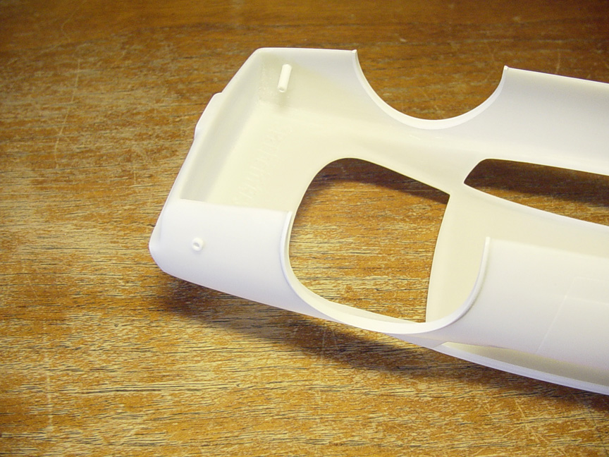
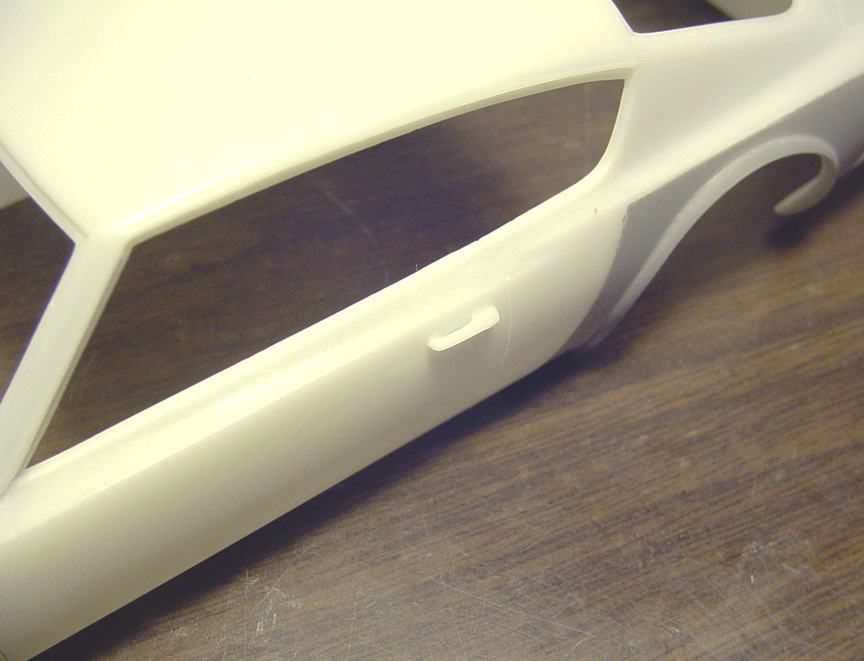
The '66 Chevelle 300 Deluxe Sedan Post body has different shaped front wheel wells than a Super Sport.
 After cleaning up all the body work and sanding down the chrome moldings on all 4 wheel wells,
Plastic strip was used to recreate the shapes of the new "Chevoom Chevelle" wheel wells.
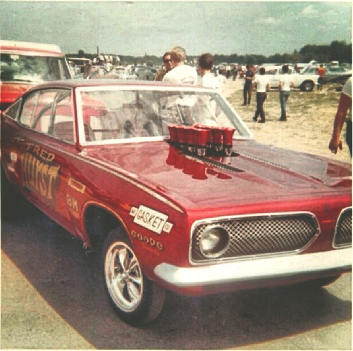
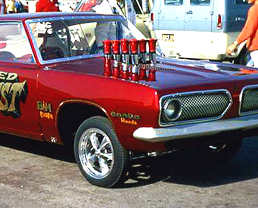
Compare the new wheel well shapes to this photo.

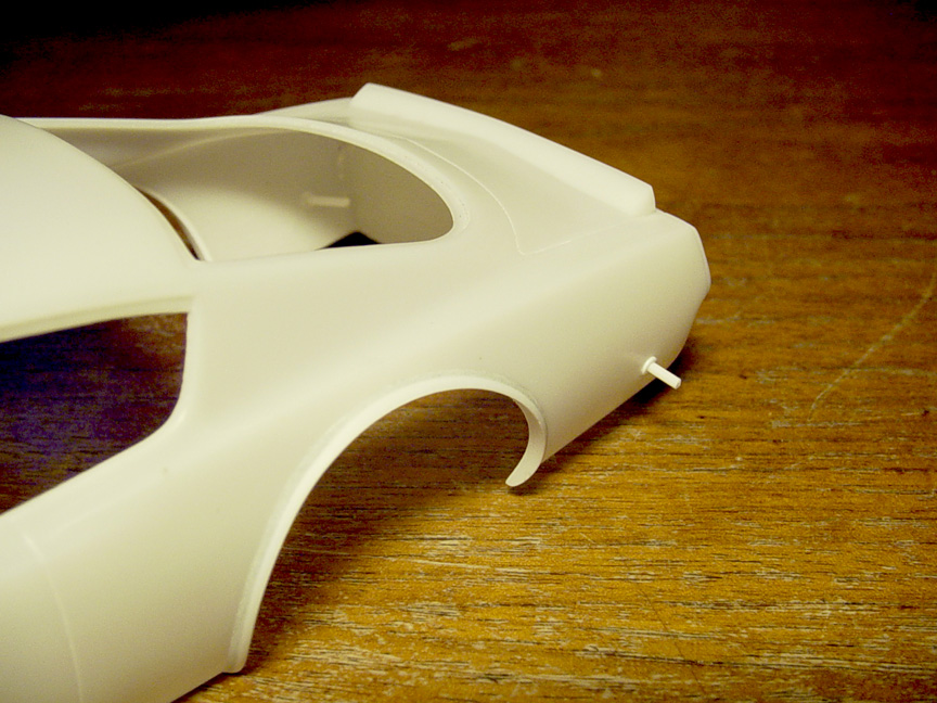
 You can see in these photos how the valance has a space and a chrome strip between the grill & bumper.
 Here is the Lindburg '66 Chevelle's valance. Notice how there is NO chrome strip or even correct spacing between the grill & bumper.

 Starting with removing the Lindburg chassis' valance and gluing it to the master body,
I added 11 additional pieces of plastic to create a new valance that will be molded to the body, including a new chrome strip.
I'm leaving the valance go all the way to the bottom for strength on the master.
 The bumperettes on the bumper will need to be removed.
After paint, you'll need to add BMF to the center molding strip between the grill & bumper, or strip it and spray with chrome.
 Putting on our signature "Semi Hollow Door Handles".
Although the Lindburg '66 Chevelle comes with separate chrome door handles, by the time you clean them up,
the chrome is ruined and there's a good chance that someday you'll grab it wrong and they will fall off.
Now that they are part of the body, there's no way these will get knocked off. Just apply some Bare Metal Foil to them.
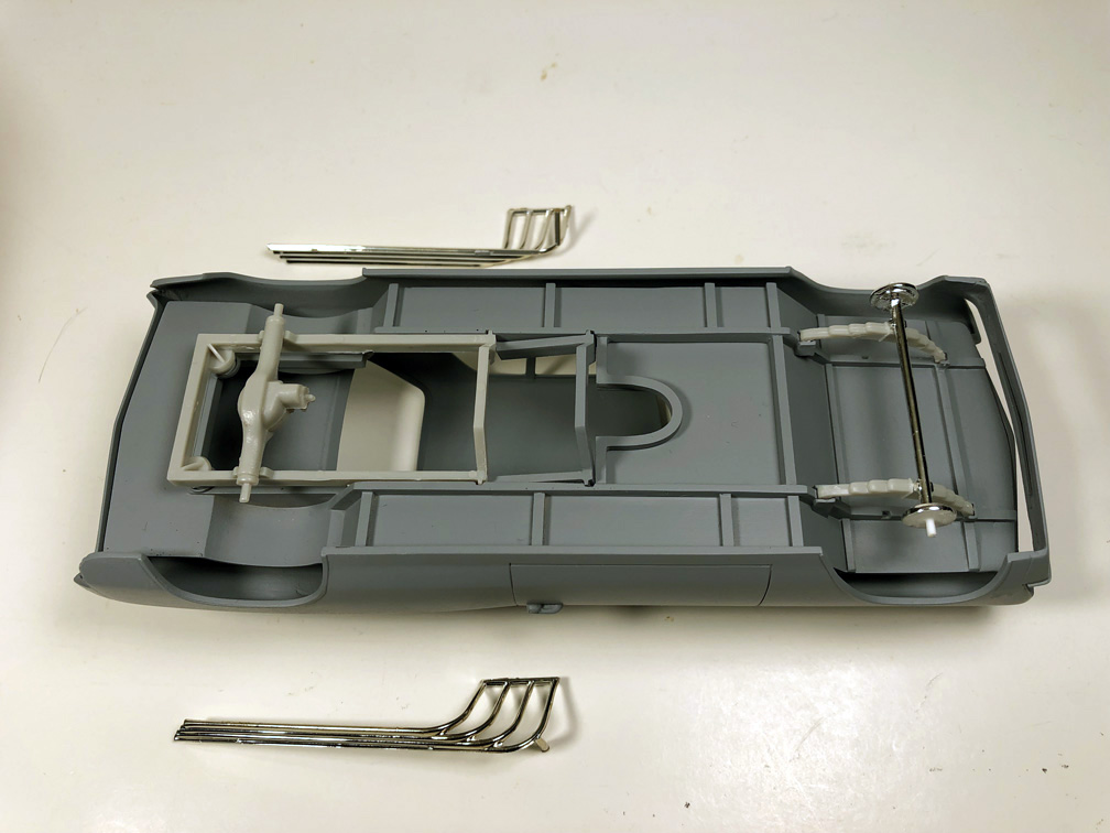
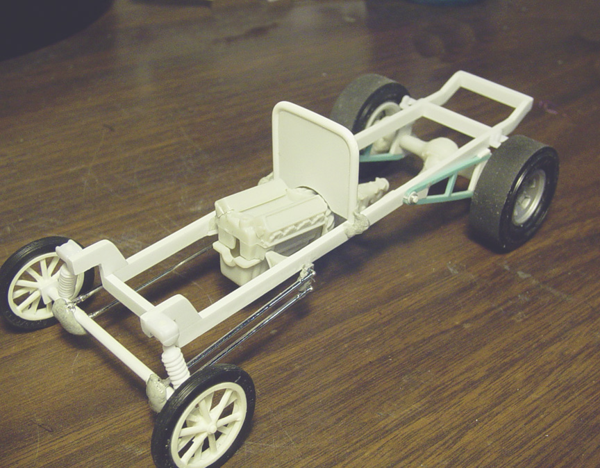
CHASSIS
 Here's the actual chassis for the Chevoom Chevelle Funny Car.
As you can see, it would take a lot of labor to create a replica chassis with plastic round tube..... And round tubes don't cast well.
Besides that, it would be too costly to cast it all.
I'm looking for an easier solution; and since you can't see much of the chassis when the model is finished anyway,
I want to create an "Easy Builder" simplified chassis that can be used in conjunction with an AMT Hemi Under Glass or Corvair Funny Car donor model.
 Here's what I came up with.....
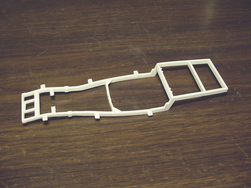
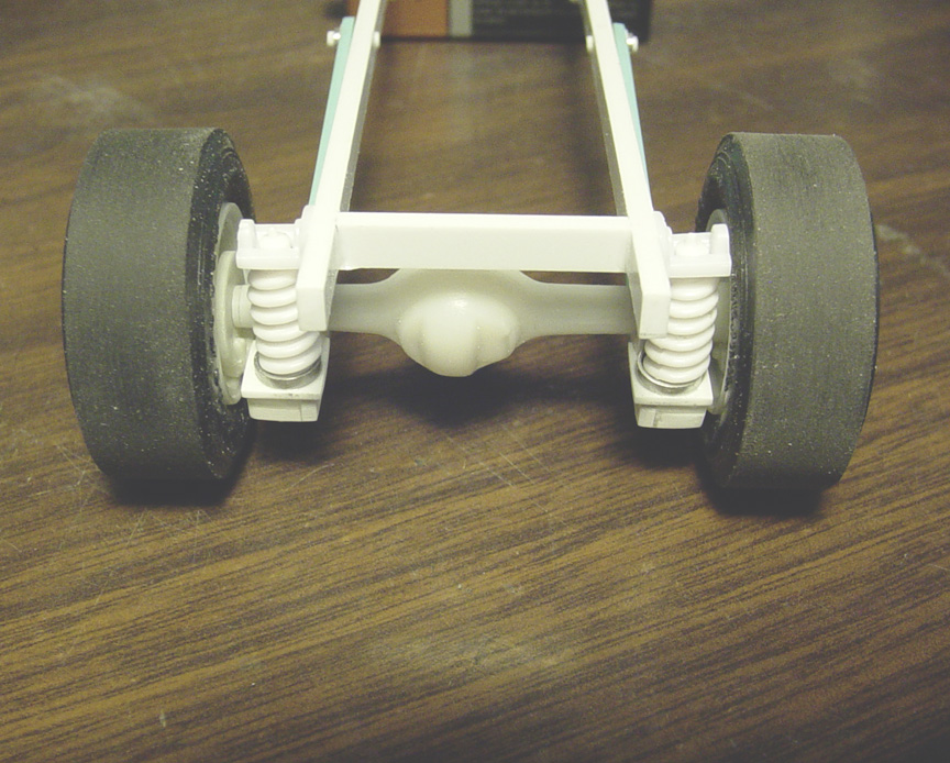
I'm going to use 2 of these Speed City Resin chassis' from our '65 (rear engine) Barracuda Funny Car (shown here).
 I used the rear of an older tan resin chassis and the front of a white resin chassis.
After sanding both sides flat, I needed to add an extra .040" x .188 plastic strip to get the wheelbase correct.
The front was filled with sheet plastic and square tube, so it can rest on the fenders.
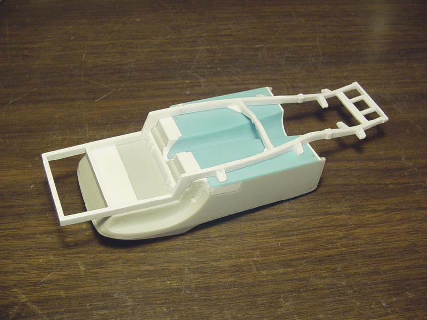
The wheelbase was set using the suspension parts from the AMT Hemi Under Glass / Corvair Funny Car.
 The wheelbase is now dead center and the correct height has been set.
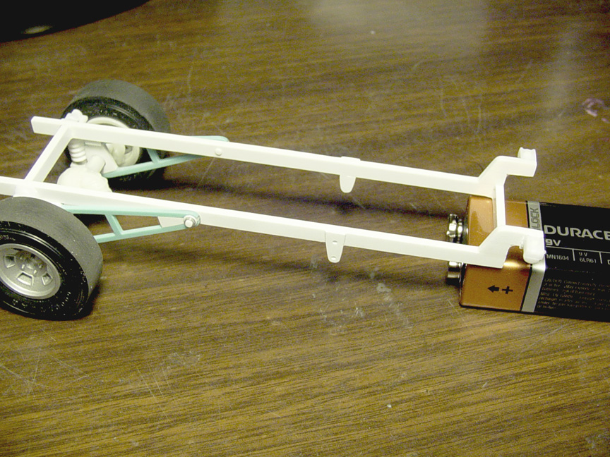
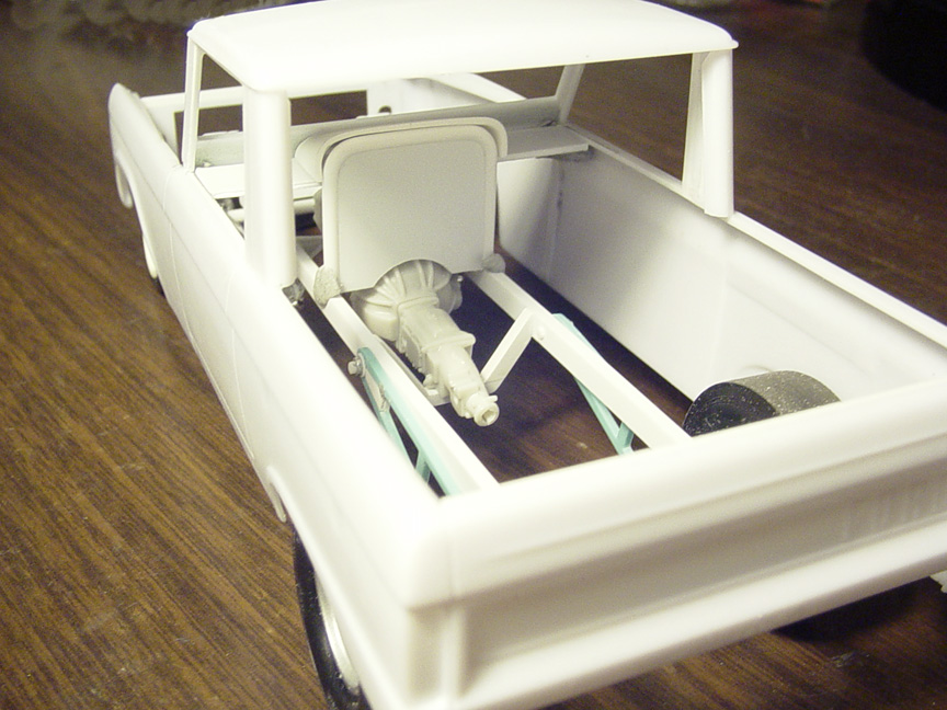
 Before moving to the interior tub, I need to figure out where the engine needs to land ?
After studying photo's, The engine sits in the middle of the firewall, where the B Pillar is.
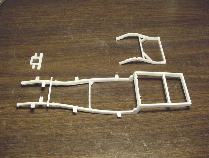
In this case, the sub-frame will need to be lengthened.
To make this easy and cost effective, I'm adding a piece from another AMT Hemi Under Glass/ Corvair F/C sub-frame as an extension piece.
You (the customer) will need to glue this to your H.U.G. or Corvair Funny Car donor kit's sub-frame.
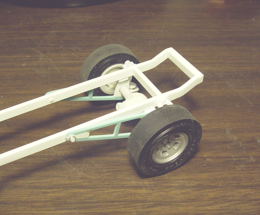
 The old frame rails were removed and new frame rails were installed to match the new roll bar locations.
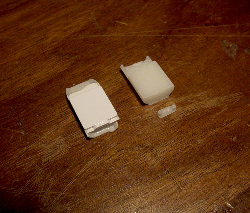
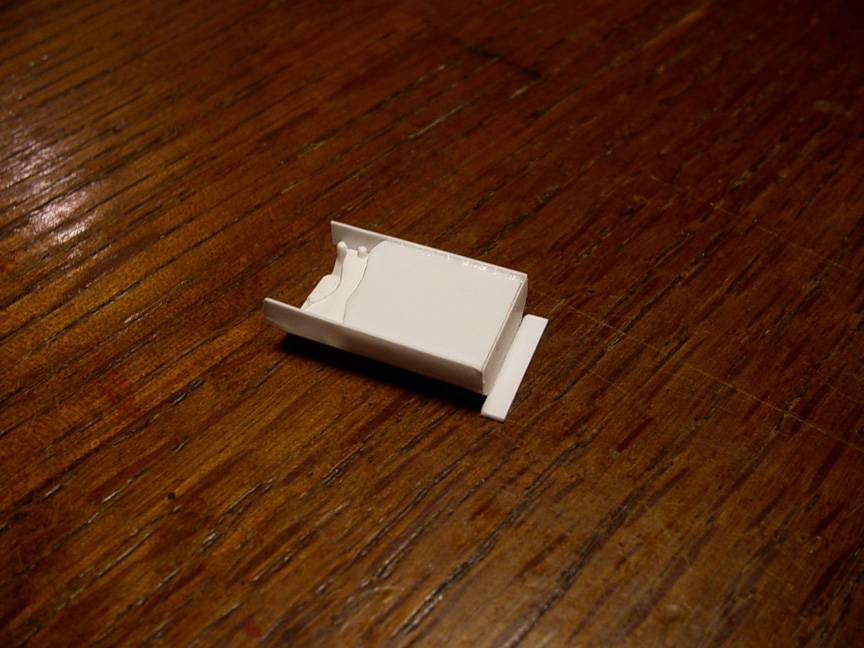
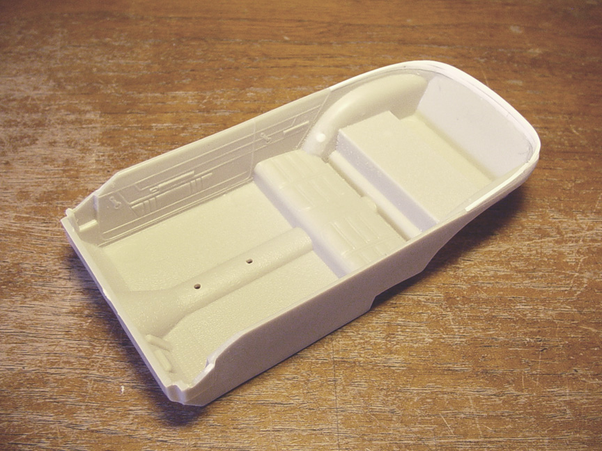
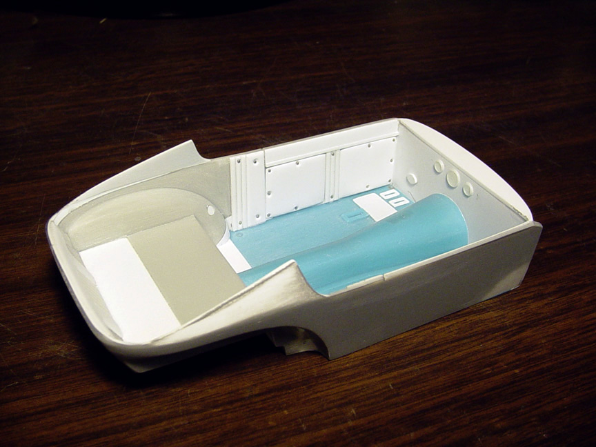
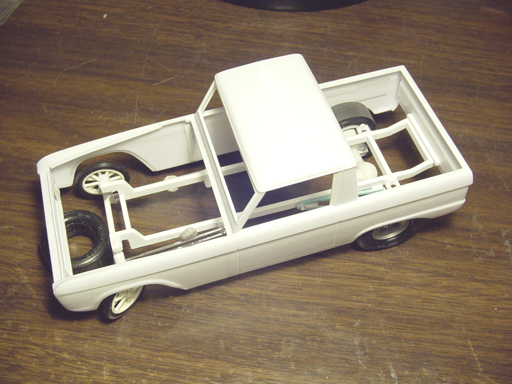
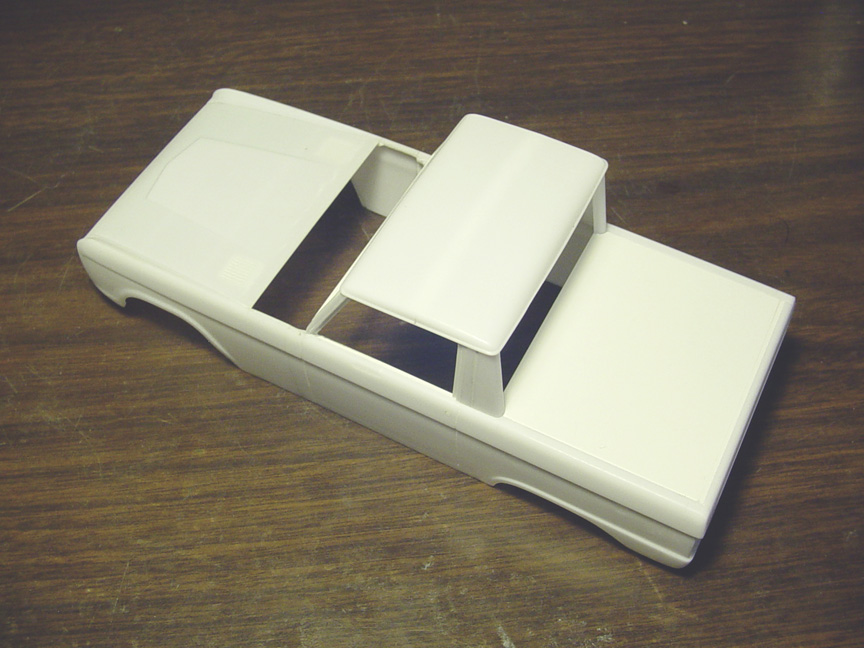
INTERIOR TUB
 A lot of planning, measuring and test fitting went into making the interior tub; and a lot of things had to be considered here.
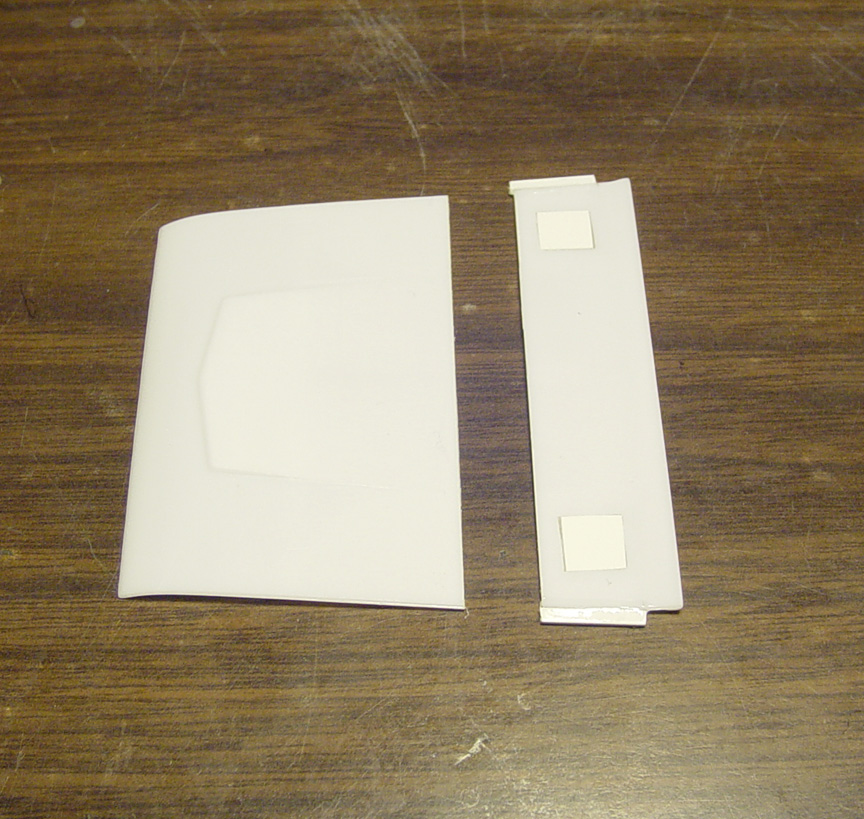
After making a new floor pan; door panels were used from the Lindburg 1966 Chevelle Super Sport.
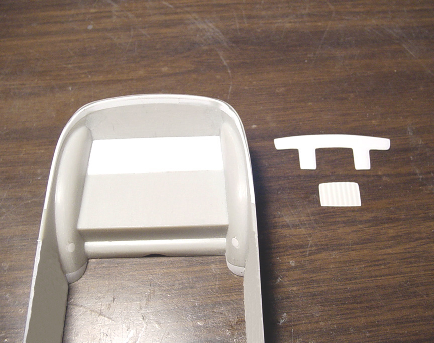
To make the door panels fit the new interior floor; I removed the bottom of the door panel, at the bottom of the door line.
The rear section of the door panel was removed and cut on an angle as the firewall will be on an angle to match the B Pillar's angle.
The vents, arm rests, window cranks and door handles (except the drivers side) were all removed. After that; all new panel lines had to be re-scribed in.
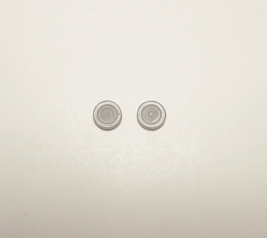
 An "RB Motion" Detail Washer was added in place of the door handle.
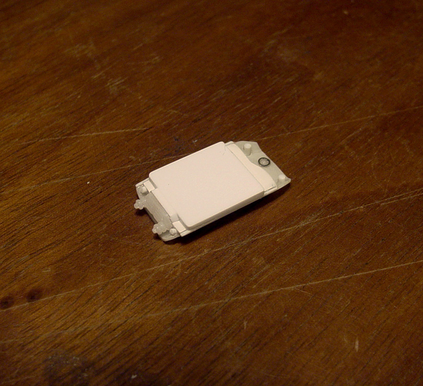
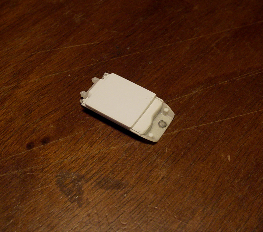
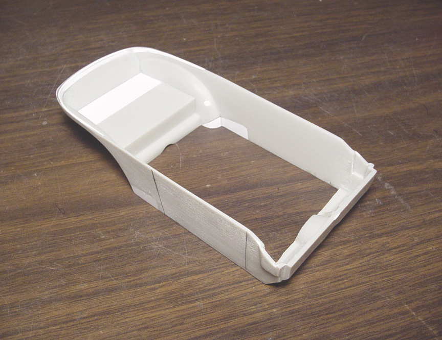
 I wasn't happy about the interior tub, so I patched in a piece to make it more square; and better match the looped frame rail.
The 1:1 Chevoom has a frame loop in front of the engine, so a frame loop was added using sq. tube. This also made the chassis more stable.
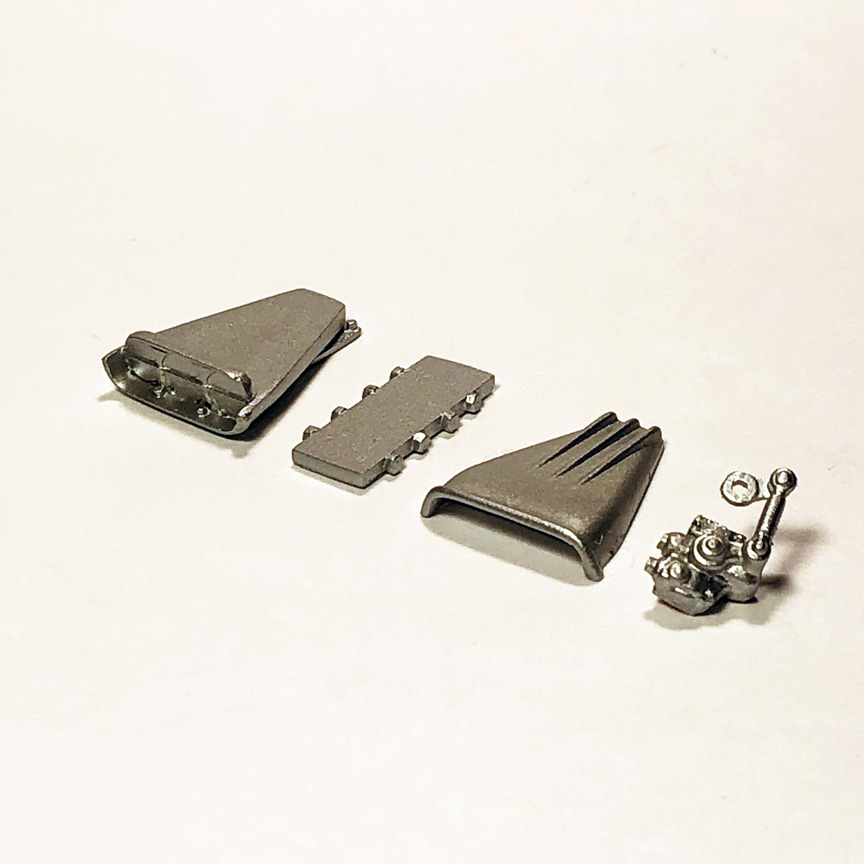
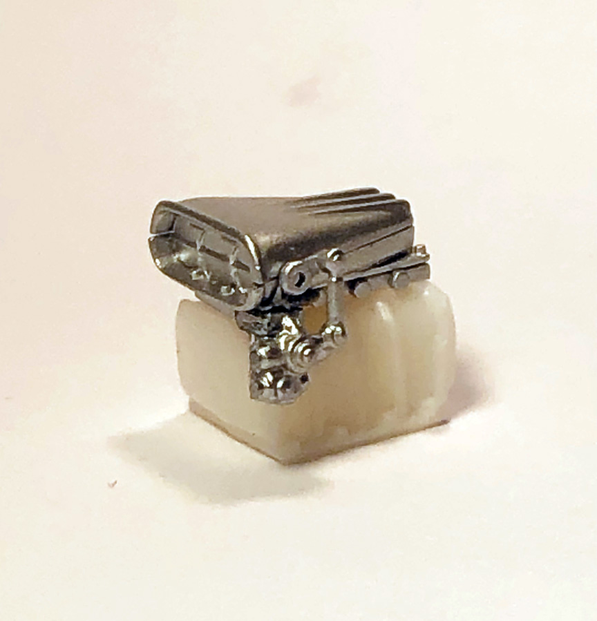
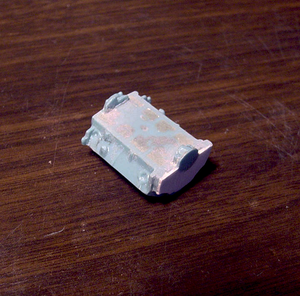
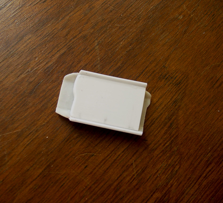
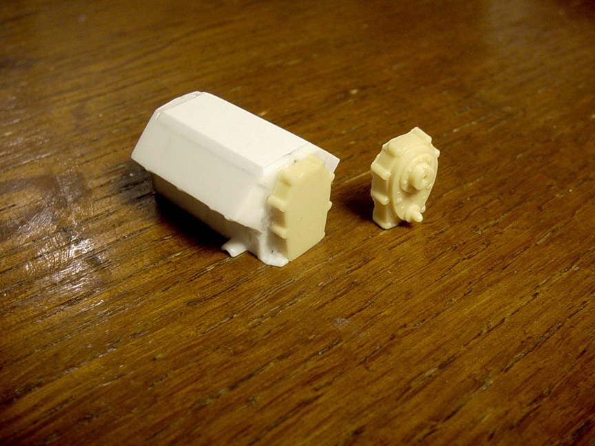
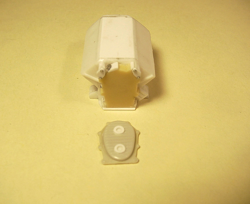
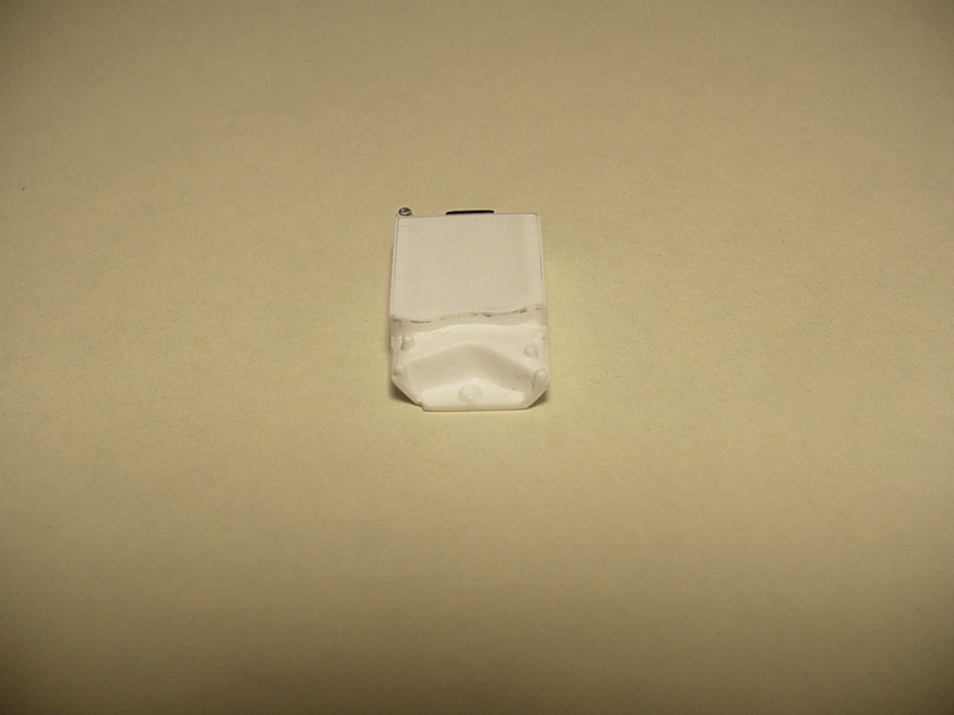
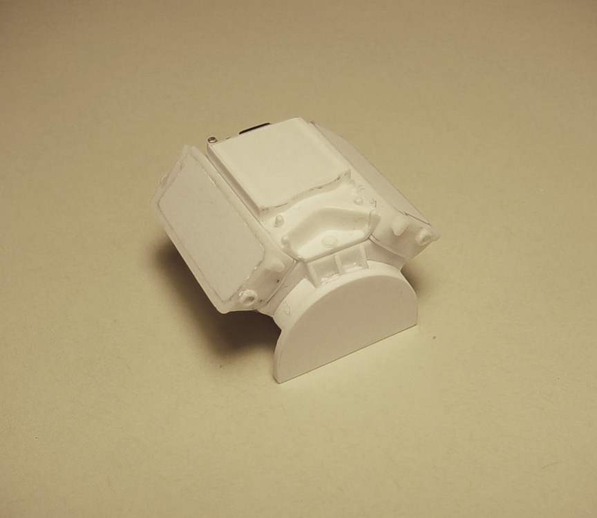
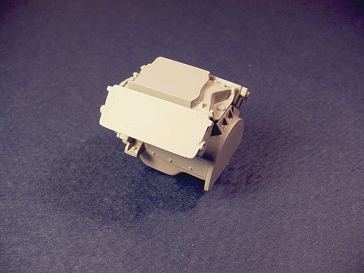
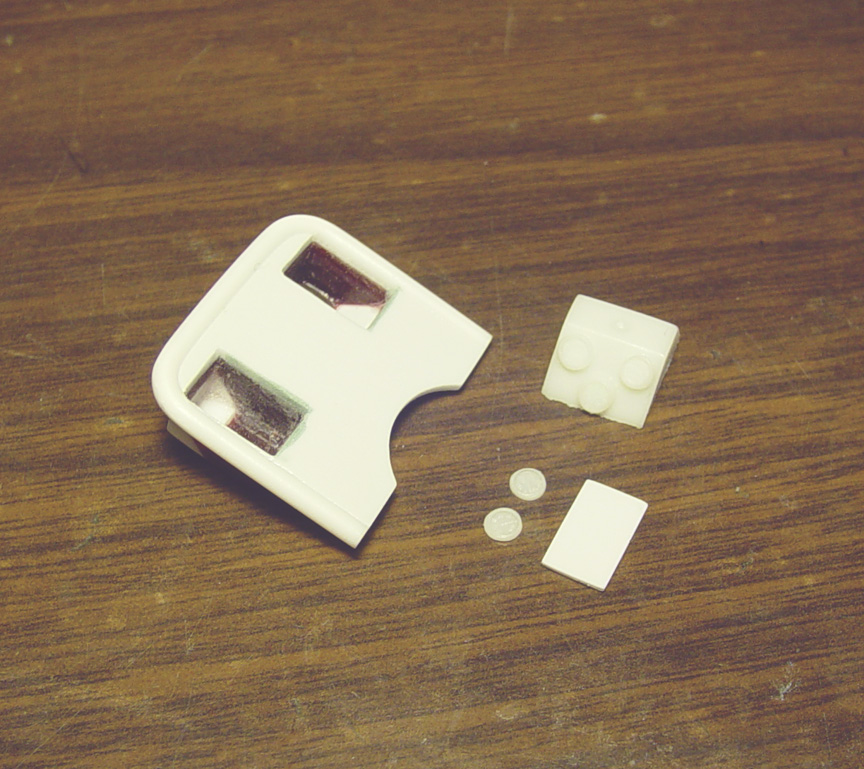
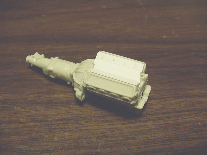
ENGINE SURROUND / DOG HOUSE
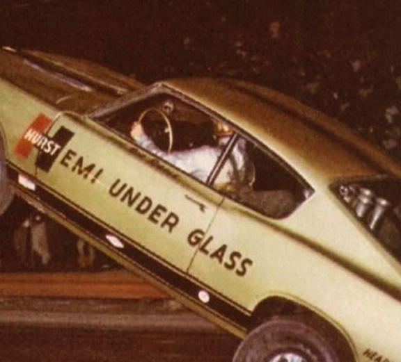
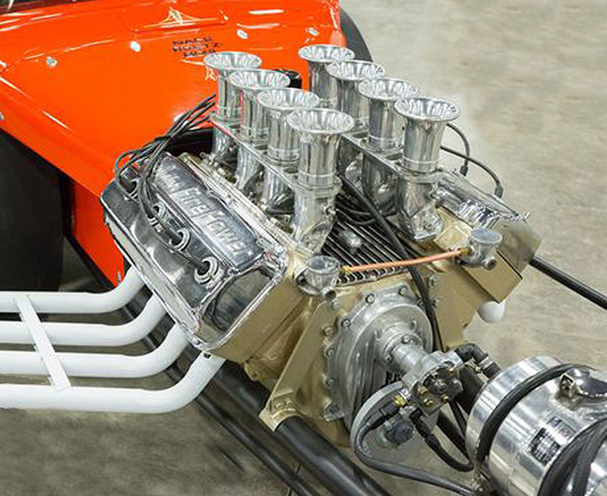
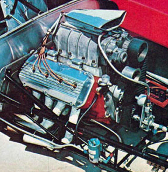
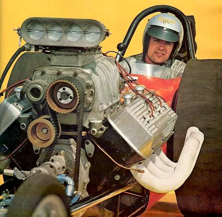
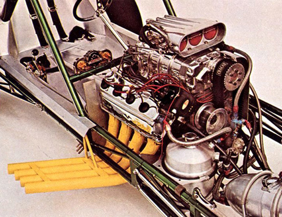
 Using this photo and other original photos for reference material;
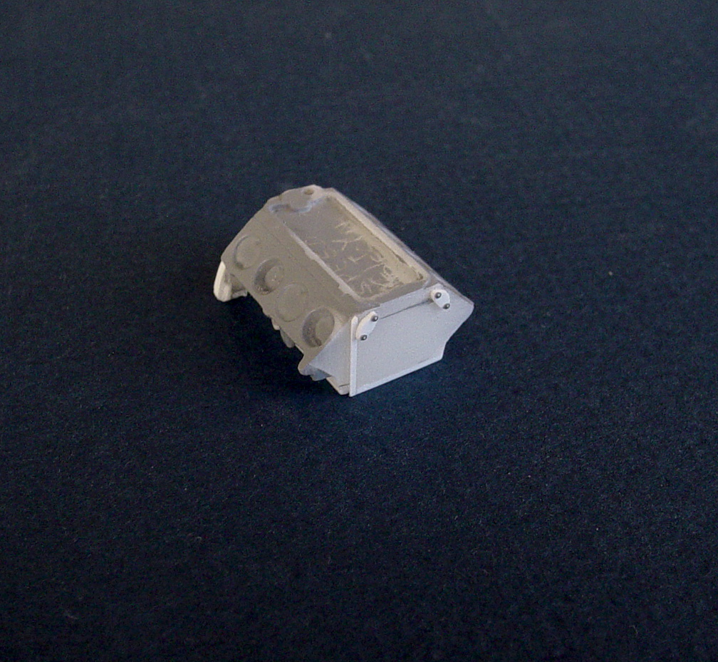
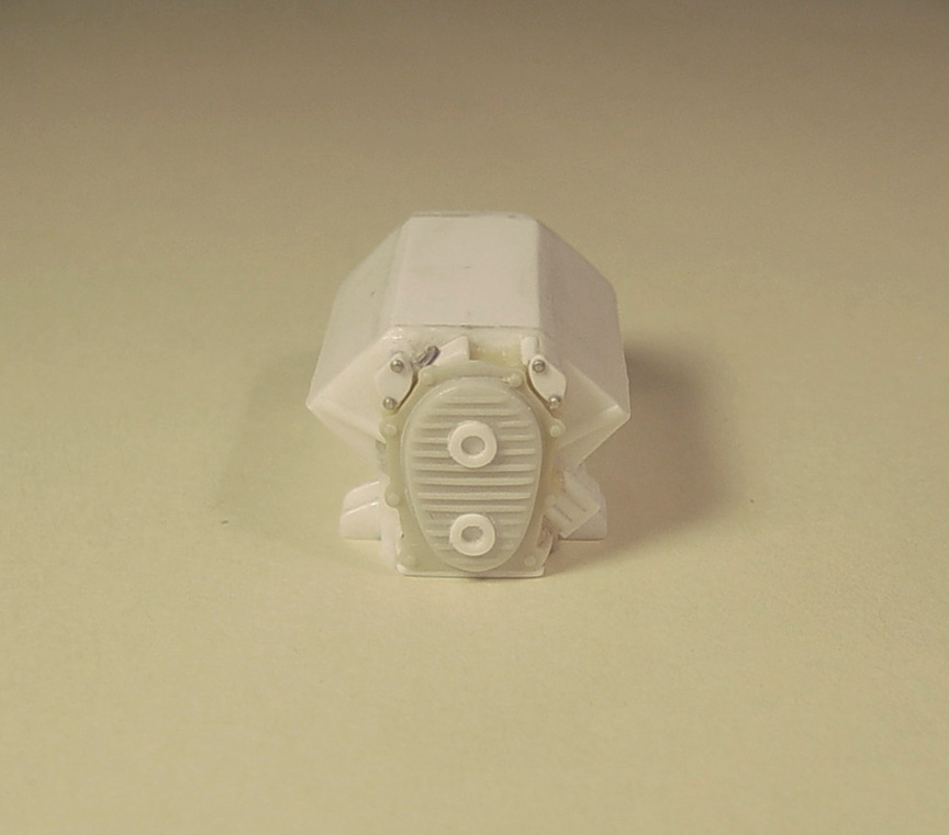
I had to make sure that the engine and rocker covers would fit the sides of the dog house.
Again, massive amounts of planning, measuring and test fitting went into making this piece.
I spent at least 2 weeks making sure this piece was correct and would fit all the engine parts.
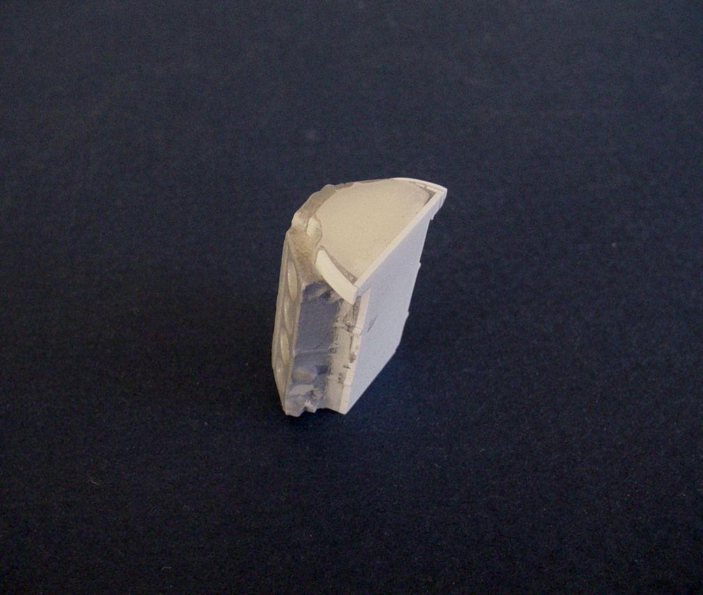
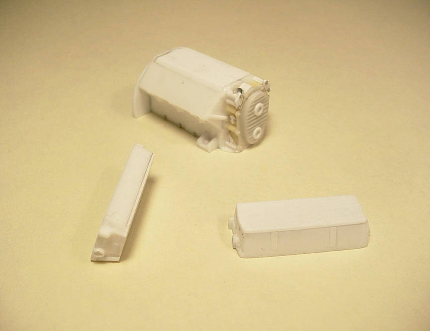
14 pieces of plastic sheet and V angle went into making it.
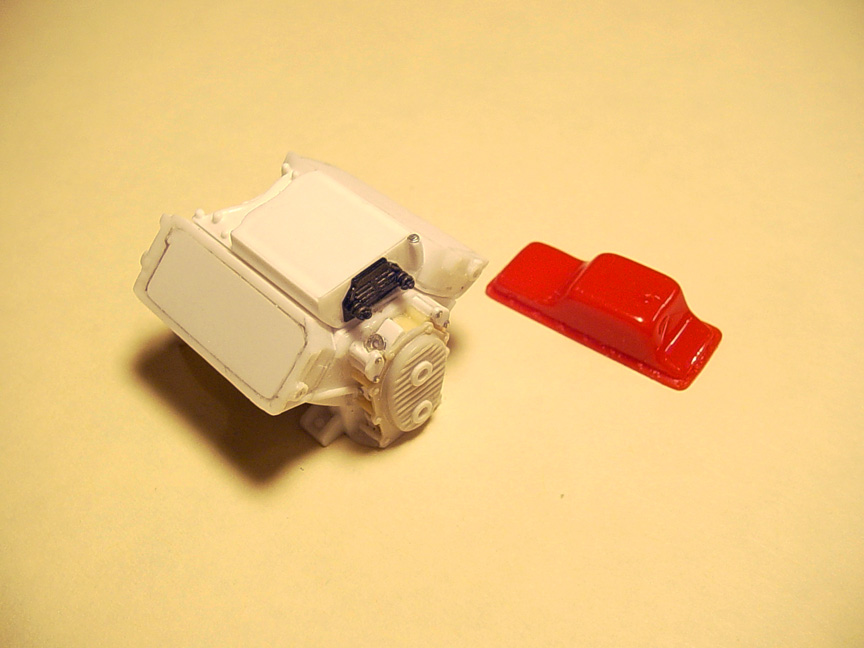
I'm also going to have the sponsor decals made that are on this Engine Surround / Dog House.

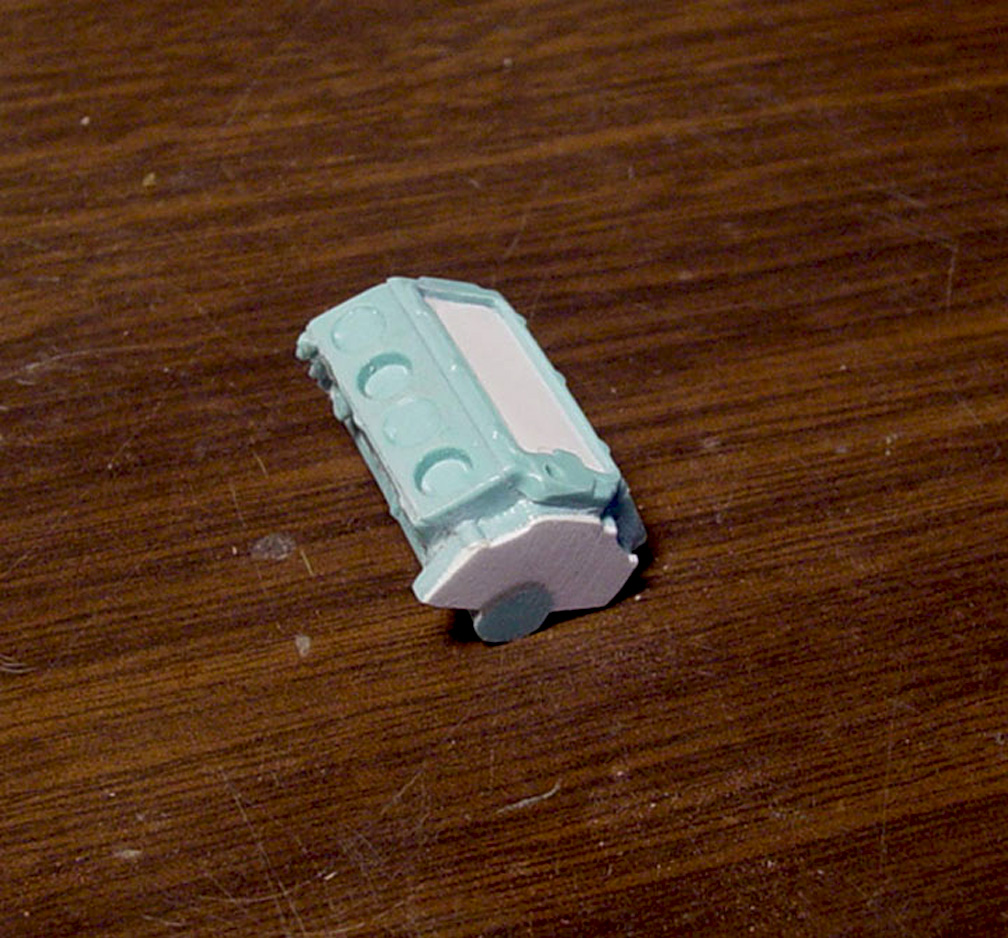
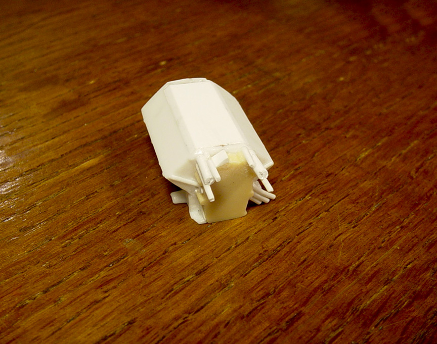
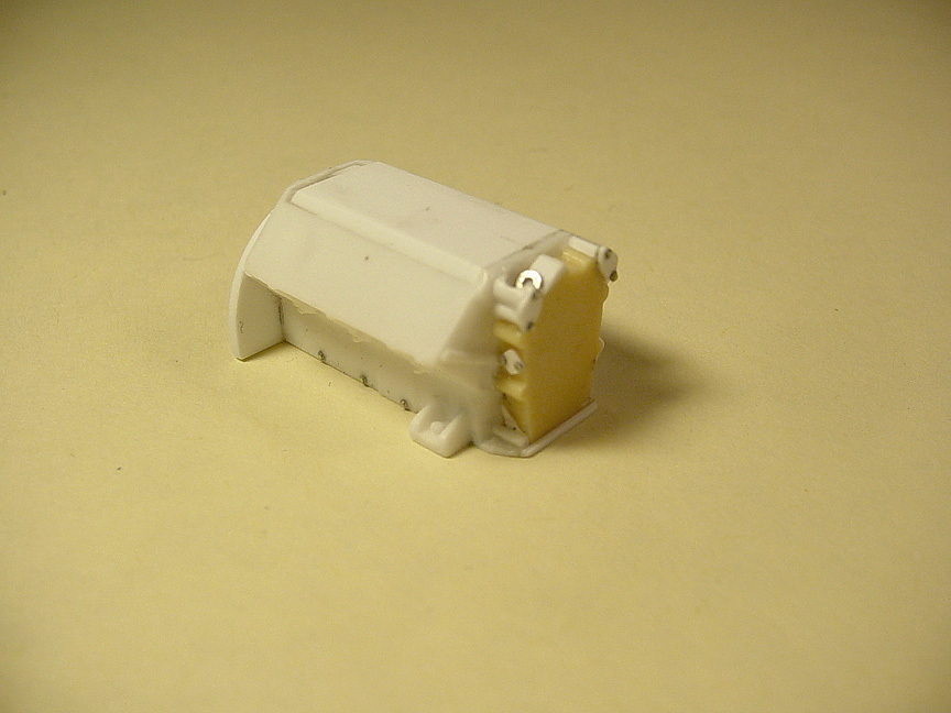
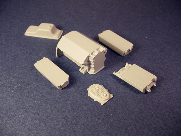
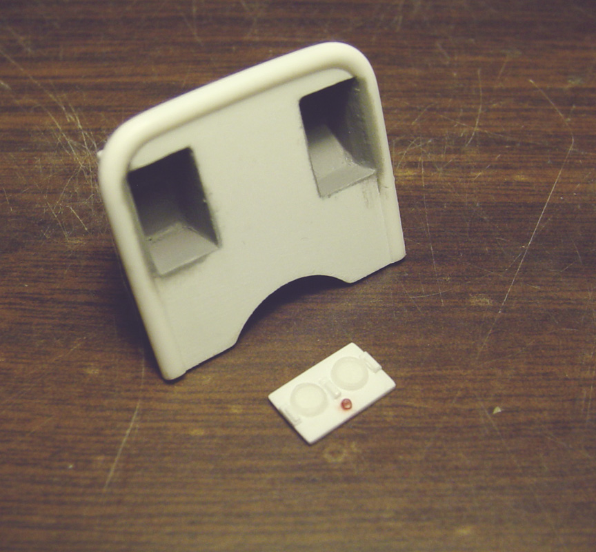
 Engine Surround / Dog House !
MASTER IS FINISHED !

Now available !


Unsatisfied with my previous "Enderle Bug Catcher" that was modified from a late 60's MPC Funny Car,
It was too tall and incorrectly shaped, so I decided to start over and make a correct one!
After spending days of getting information and research, I believe I've came up with the best solution possible in 1/25 scale.
This is the old Speed City Resin "Enderle Bug Catcher".
At the time I put it into production, I didn't realize how wrong it was.
But, it was still the best Enderle Bug Catcher aftermarket piece available back then.
 Starting with the nicest blower hat I could find; was from an undisclosed 1980's AMT Funny Car 2- piece blower.
 This Bug Catcher is more accurate than any other one we could find, and looks better than our previous one.
(New Bug Catcher is shown on the Terrifying Toronado mock up).
 It was de-chromed and I punched out 3.5 mm on .020" sheet to create backing plates for the butterflies.
 .010" sheet was added to the top & bottom to raise the hat slightly to fit the new (punched out) butterflies.
 A spacer is being made for the butterflies face.
.010" round is being used for the rod.
 Another set of butterflies are added to bring them closer to the front.
 Here's how the 2 pieces will fit together.
 4- MENG Bolt Heads are added to the base. A detail NO other blower hat has ever had !

 Here you see the top & bottom of the hat half's.
 Blower Hat half's are finished.
 This is a K-style Barrel Valve that that will be included in our *parts pack*.

 A new "Barrel Valve" front & back.
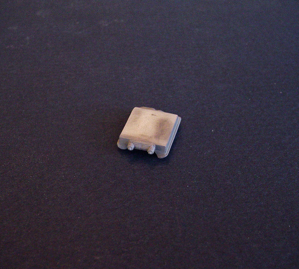
 The "Adaptor Base Plate" is made from .040" sheet and 8- MENG Bolt Heads were added to the sides.
With this set up, you can do 3 different style Enderle set up's.
When using the base you will need to add your own Fuel Block using a plastic square strip.
MASTER IS FINISHED !


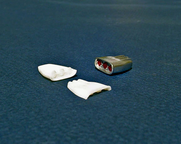
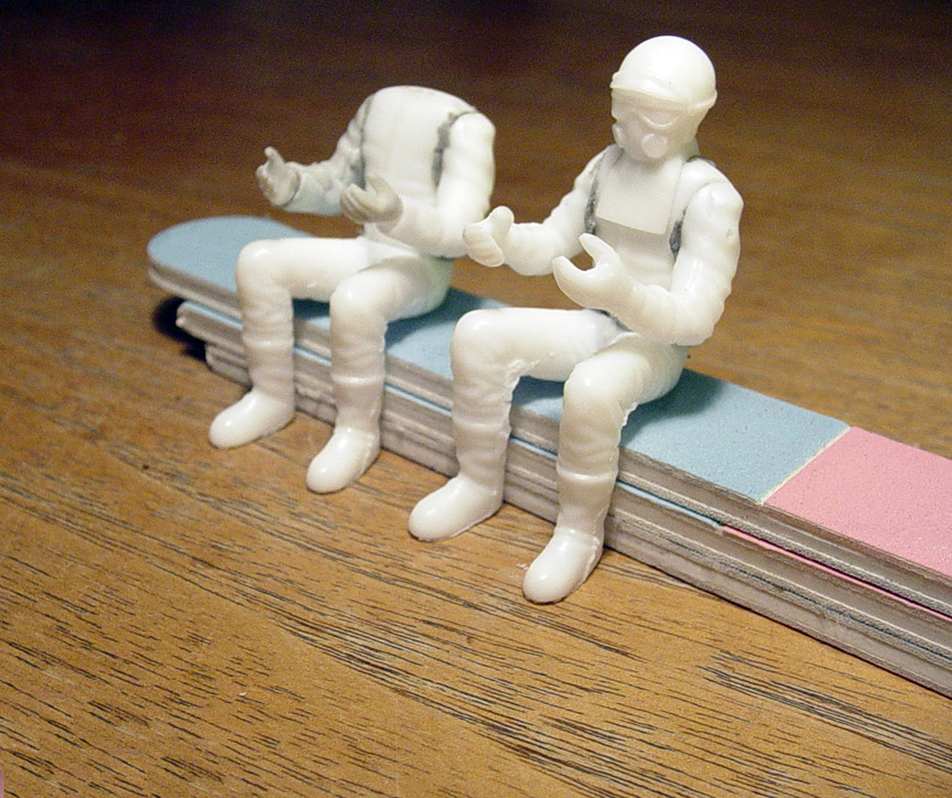
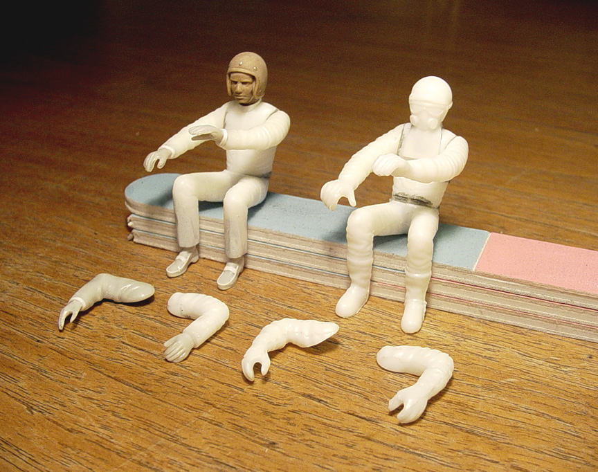
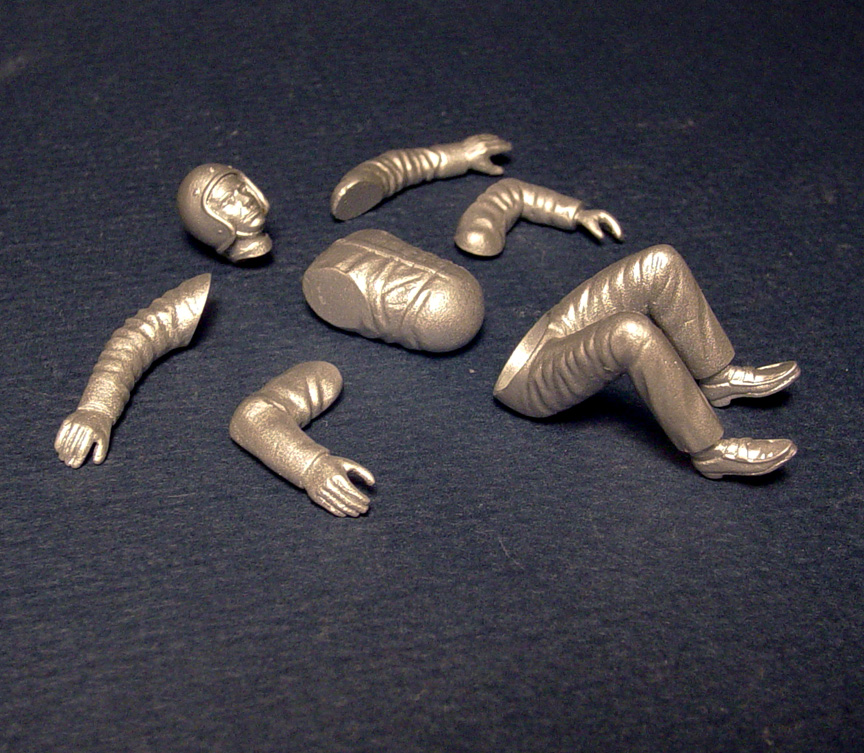
This new Driver Figure will be designed for early drag cars, such as: AFXer's, GASSER's, SUPER STOCK's and WHEELSTANDER's !
This new figure will come with; Open Face, Bare Hands, Penny Loafer Shoes, Standard Helmet & Fire Suit.
Like our previous Driver Figure; It will come with two sets of arms - * bent and extended arms*- and have the same - "Ball & Socket" - hip and torso.
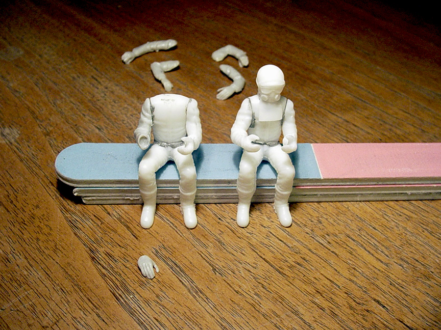 Our original "Drag Racing Driver Figure #2" (shown on the right) will be used as a guide for our new "early style" Drag Figure #1.
I'll be using arms and feet from a couple of MPC "GANG BUSTERS" 1920's model kits that I have been saving for this project for many years.
The MPC Gang Busters right arm had the same angle as our original driver figure, but the hand was in the wrong location.
The hand was cut off and the arm was drilled out to accept the hand in a different angle.
 The left arm had the glove hand removed and a new "bare hand" from the Gang Busters kit was installed with the same angle as our original figure.
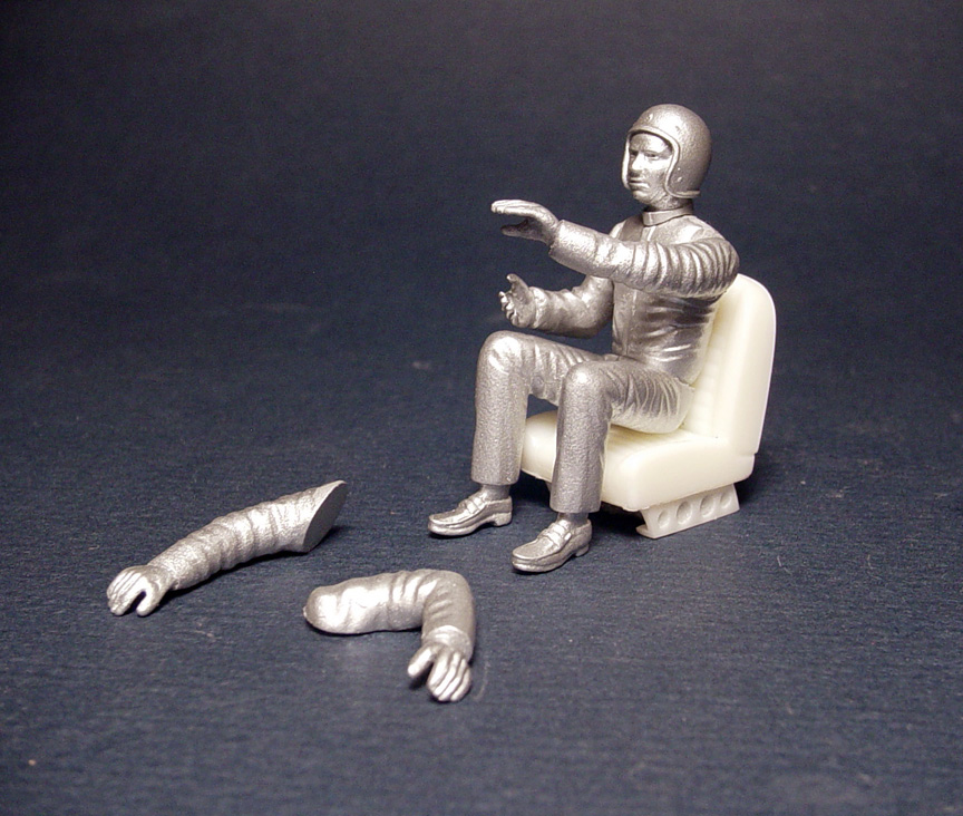
BTW.... The body parts are all being held together with "QUAKE HOLD".
Quake Hold can also be used when manipulating your figure to fit your seat and steering wheel.
 Now instead of gloves, the new figure will have bare hands.
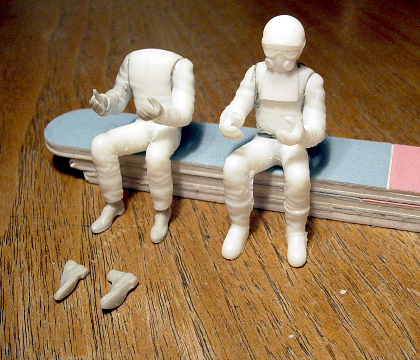
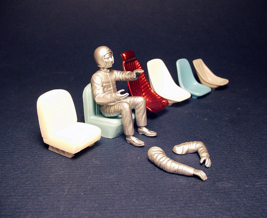
To make the legs the same height as the original figures legs, one boot was removed at a time.
Each boot was removed and the shoes from the MPC Gang Busters were added.
My plan is to make these shoes look like Penny Loafers from the 60's, as it seemed that everyone was wearing penny loafers back then!
 Using the shoes from the Gang Busters kit...... These shoes were very mis-shaped and will need some work to make them look good.
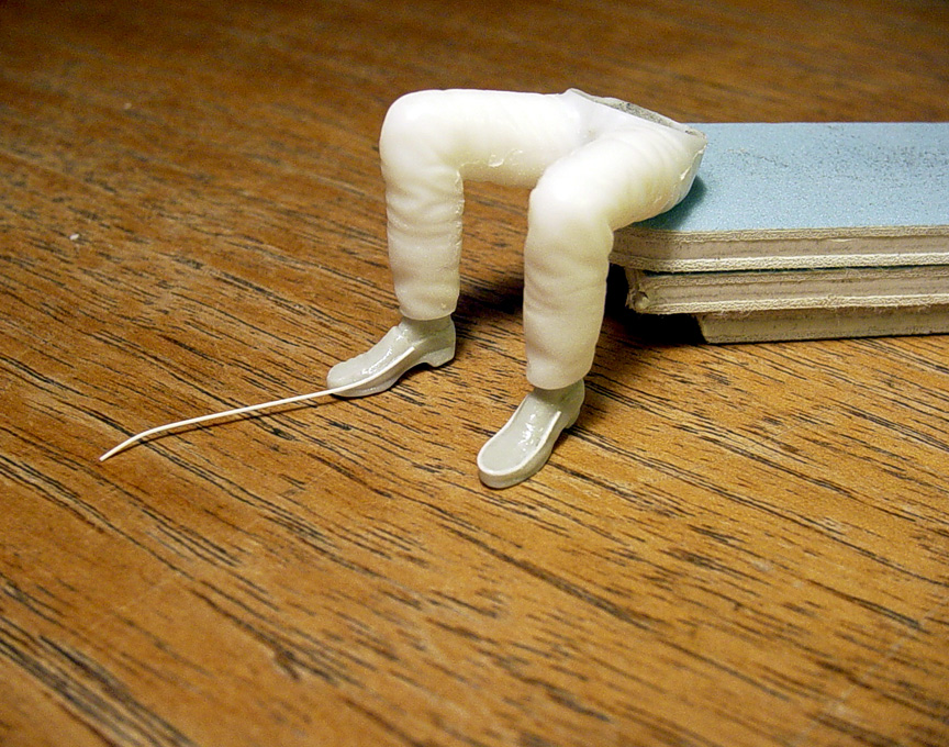 The wrinkles on the pants legs were sanded down.
Super Glue is added to the side & tops of the shoes to make them thicker and more uniform.
.010" round is being added to the sides of each shoe to make the shoes look more like vintage Penny Loafers.
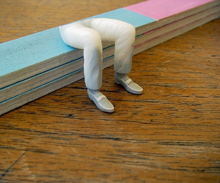 The pants legs were built up and smoothed out with putty.
The tops of the penny loafers (were the penny goes) were created with .010" sheet plastic.
 To make the arms & hands uniform to the original arms & hands, the extended arms from the original figure were glued to a sheet of plastic.
2 more sets hands from the Gang Busters were added to the same angle as the original arms.
 Here are the new arms with bare hands on the same angle as the original figure (with gloves).
 Starting with a 1/24 scale Formula 1 resin head, the entire helmet was reduced to 1/25 scale by sanding it all down.
The visor was removed, the helmet bead was re-scribed, photo-etch "visor" snaps were added, the nose was made smaller,
the forehead was sanded back, a neck collar was made with plastic sheet and the neck was made to fit the shoulders.
 Just needs primer and some fine tuning.
MASTER IS FINISHED !
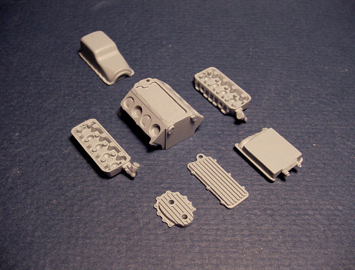
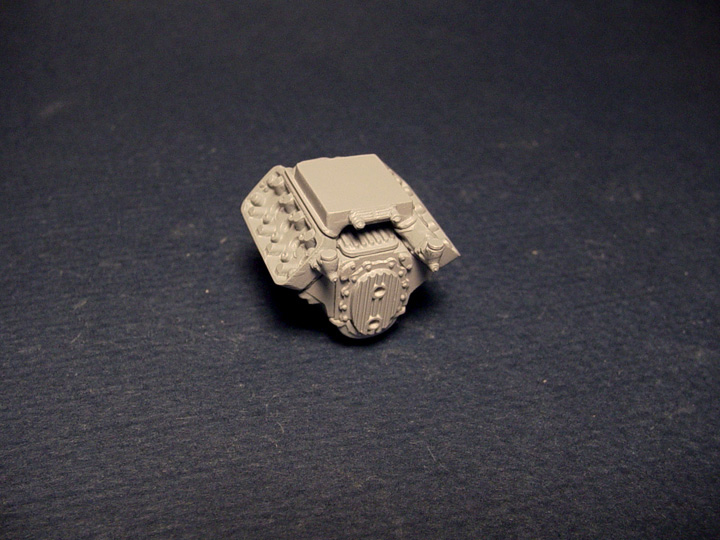
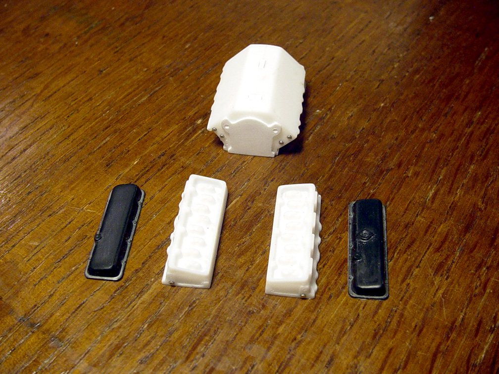
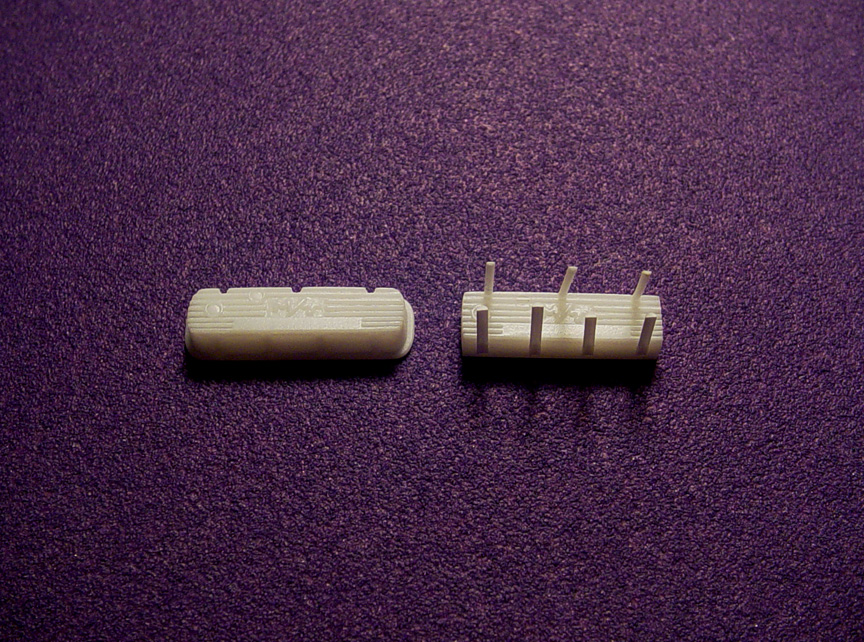
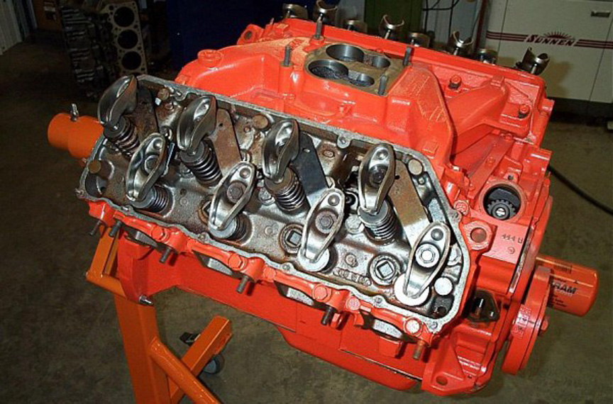
Re-working our original 392 Hemi to be even more accurate than ever !
 This was the original 392 Hemi parts I made back in 2011.
The Revell "Miss Deal" Funny Car 392 engine comes in 4-piece sections and is a real pain to assemble, putty and sand.
I made the original Speed City Resin 392 Hemi Engine as a 1-piece solid (cast-able) block (see photos).
Although it was the most convincing 1/25 scale 392 around at the time; it still lacked details that I wanted it to have.
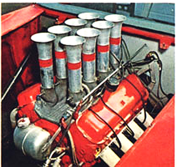
 Going off this photo, you can see the left & right "Water Port Caps" on the block and "Water Filler Tubes" on the heads.
I want to add these components to our 392 resin engine to make it a more convincing replica.
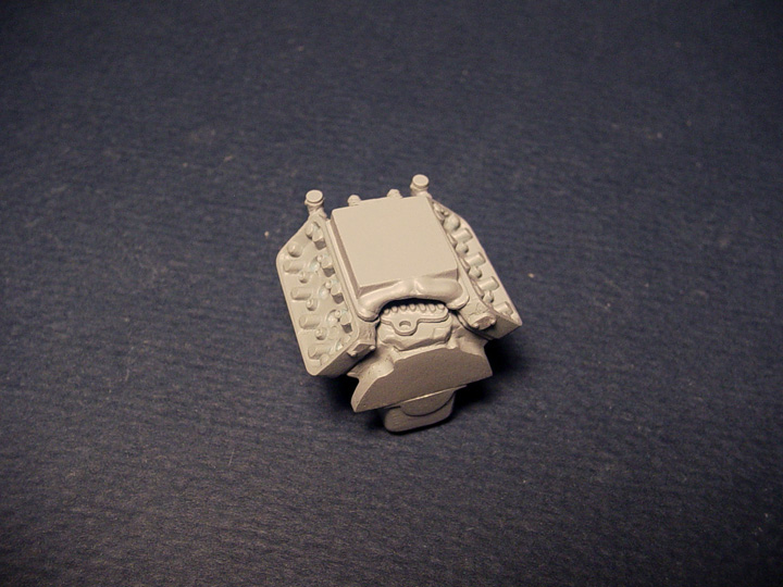
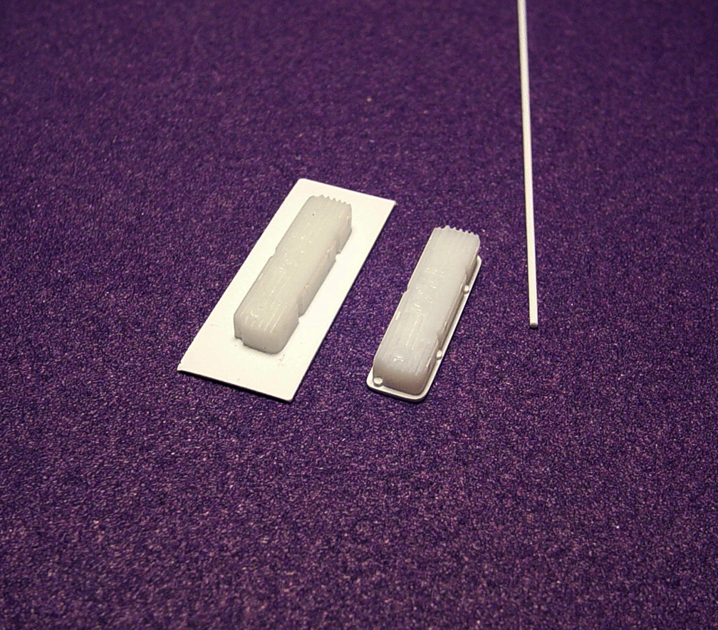
 Going back to the 392 block, I removed the 1/2 round crank detail and .030" sheet was added to the bottom of the block to make it a little taller.
 The back of the block around the transmission mounting plate needed some sheet plastic and some round tube-
to
fit the bolt pattern on our new 727 Torque Flight (short Tail)Transmission (coming soon).
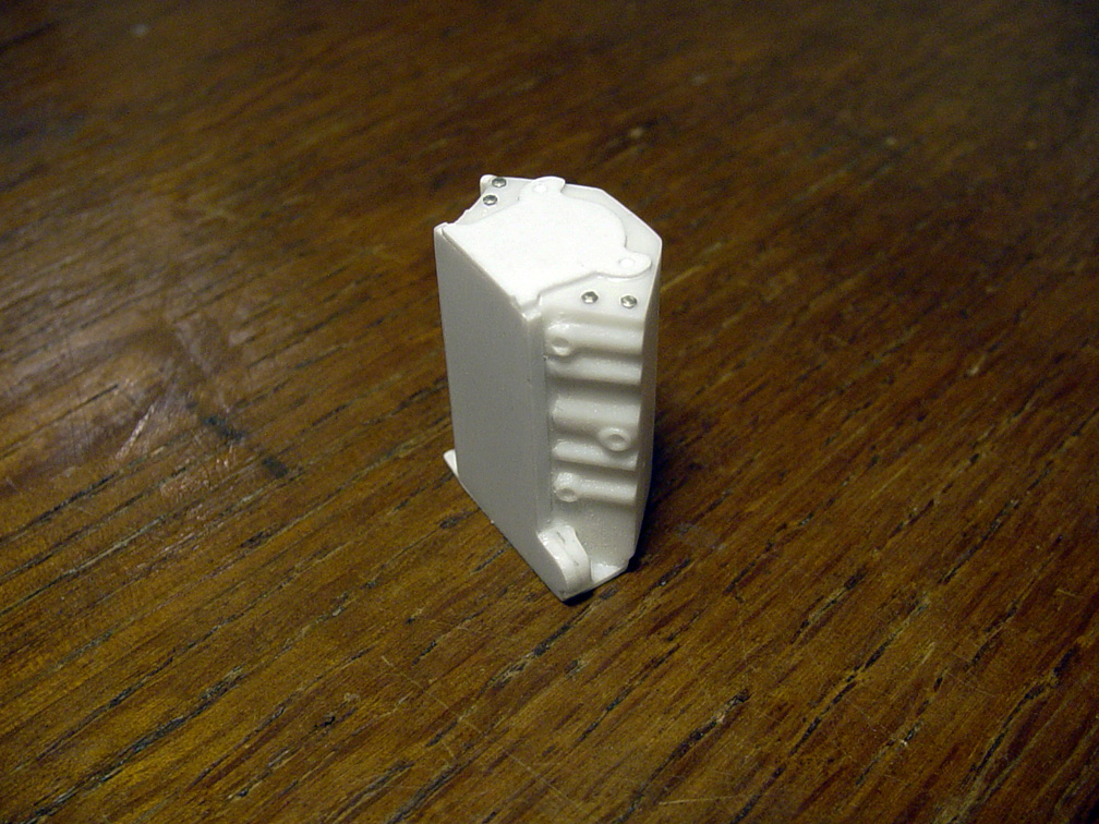
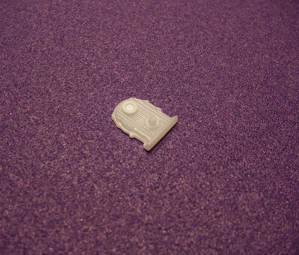
 Since the Crank detail was removed from the block, the Oil Pan had the front & rear filled in with sheet plastic and
A (PE) Photo-Etch .030" Bolt Head from Pro Tech was added for an Oil Drain Plug.
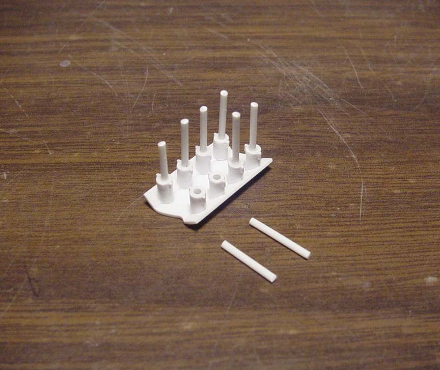
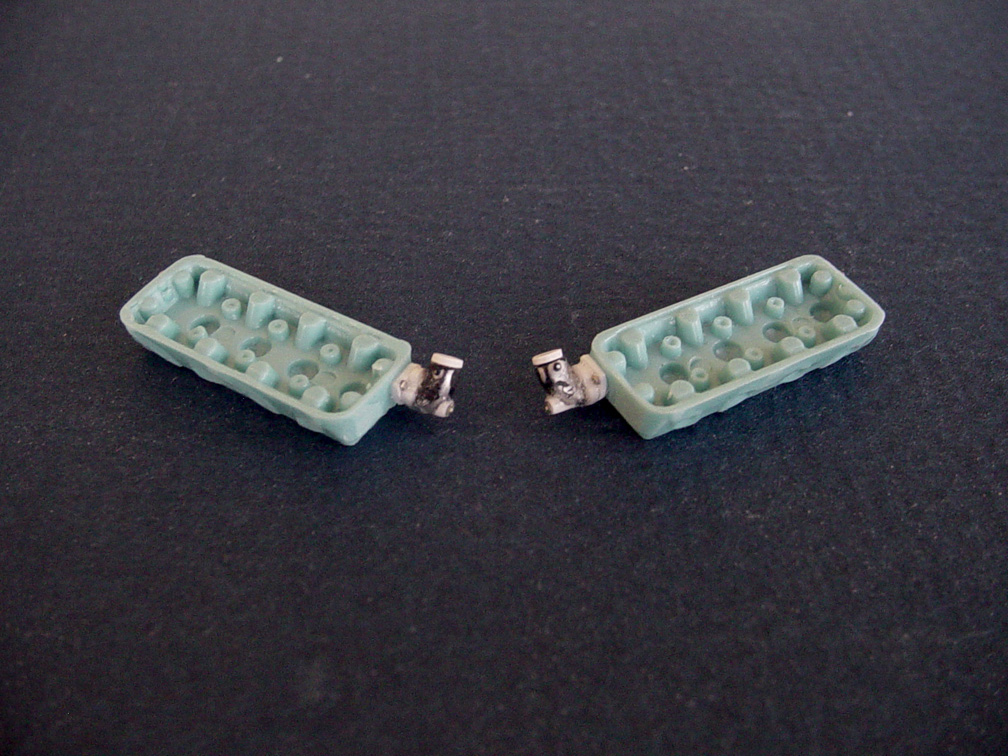 These 2 Water Filler Tubes were made from 16 separate parts. This was extremely tough... The smaller the part, the harder the job !
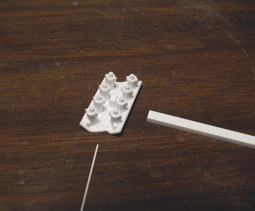
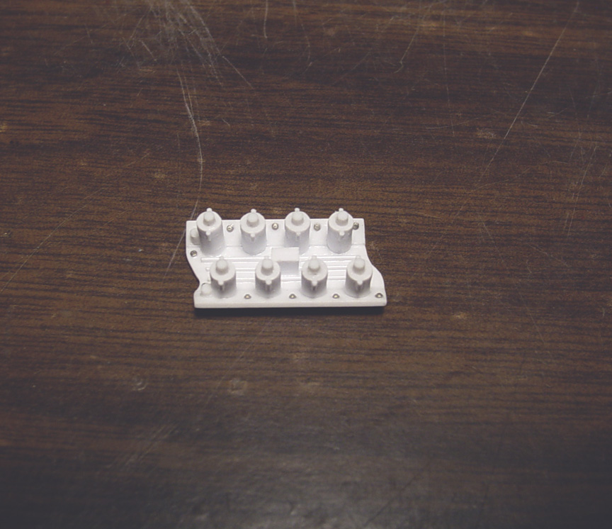
 The "Water Port Caps" on the rear of the heads were made from sheet plastic and (PE) Bolt Heads.
 A "Burst Plate (with springs)" was cut from our "Speed City Resin 426 Hemi Blower Manifold" and added to the new 392 Blower Manifold.
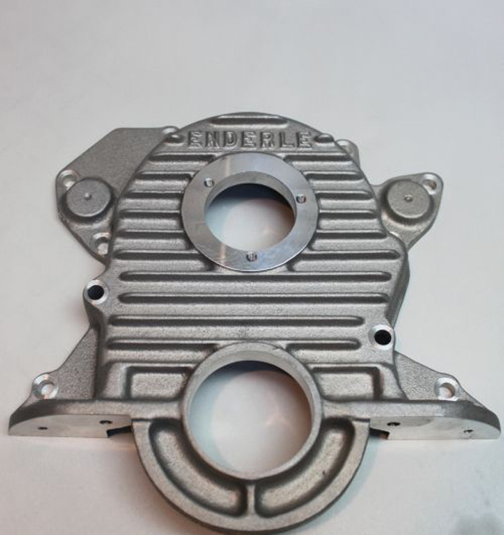
 After an extensive "non-productive" search to find a proper 392 Timing Cover;
I gave up and realized that I would need to scratch build one !
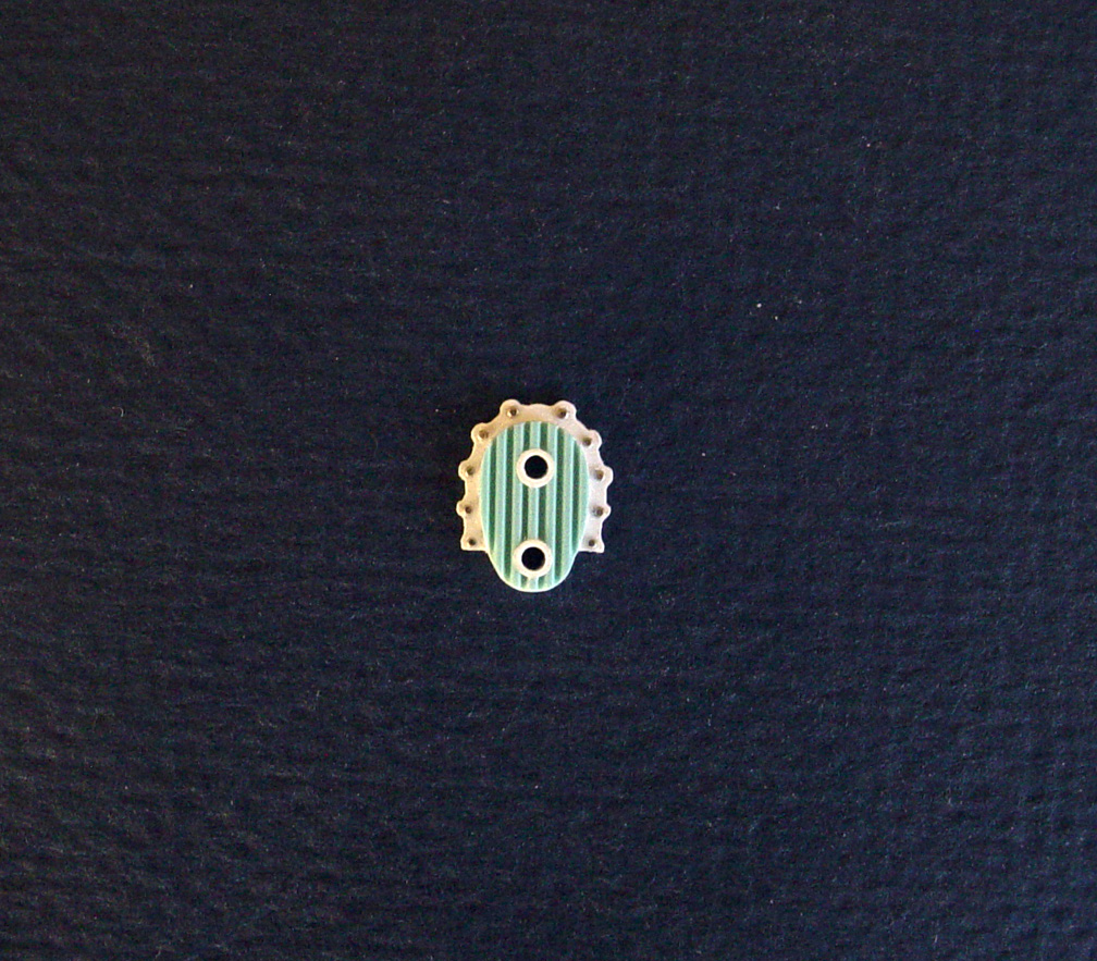
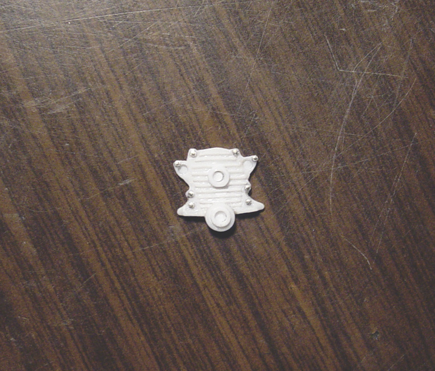
I wanted the cooling fins on the new Timing Cover to resemble the (M/T style) Finned Valley Pan.
I made the finned middle section from another "Miss Deal" Valley Pan.
Holes were drilled in the middle section and hollow round tubes were added for the Crank and the Fuel Pump locations.
More plastic sheet was used for the base and 10 (PE) Bolt Heads were added and was then shaped by hand around all the bolt heads.
MASTER IS FINISHED !

Trying to find a decent Big Block Chevy Engine in a model kit is difficult to say the least.
Seem's like all the kits with BBC engines got it wrong.
Even some 1/24 scale Big Block engines are smaller than some 1/25 scale Small Block engines.... Go figure?
We need to fix this problem as I'm sure a lot of you want (or need) a correct one.... I know I do!
This has been on my "TO DO" list for several years and it's time to do it justice.
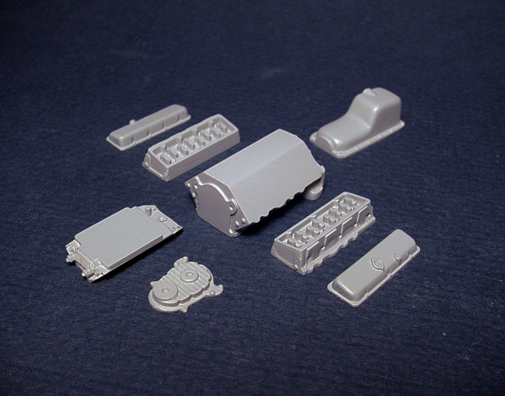
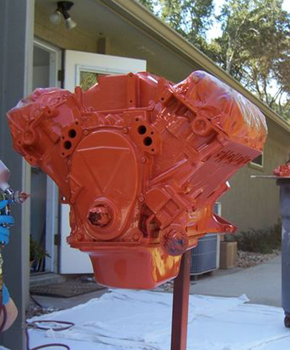
This new 1/25 scale engine will be based on a factory 1965-1969 Big Block Chevy Engine.
Mainly designed for Blown or Injected Racing Engines, this engine can be used for a stock engine by adding these kit parts;
Water Pump, Fan/Belt, Oil Filter, Intake, Carburetor & Air Cleaner.
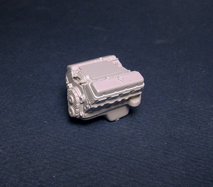
 Starting with a Lindburg '66 Chevelle 396 engine, the 4 speed transmission was cut off and 24 modifications were done to the block.
Including; adding a timing cover protrusion for the BBC Timing Cover I'll be adding later.
The rear of the block was also re-designed to except our new G.M. Turbo- HydraMatic 400 Transmission bolt pattern (COMING SOON).
 Water plugs and holes were drilled on all the faces of the heads.
Plug wire holes were pre-drilled in the heads.
The valve covers were stripped of chrome and polished out.
 The oil pan had a protrusion that was removed from the lower end.
The oil filter was also removed and a photo-etch bolt head was put on.
 I'll be adding the "Timing Cover" from our Speed City Resin "M/T BBC PART'S PACK".
BBC BLOWER MANIFOLD
After searching all my parts boxes and asking friends about where to find a decent looking BBC Blower Manifold?
I soon found out that once again; no model company or aftermarket ever made one that was even close to being accurate.
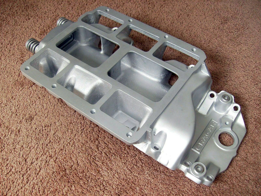
I'll be using these 2 reference photos to create a new correct one in 1/25 scale based on a CRAGAR BBC BLOWER MANIFOLD.

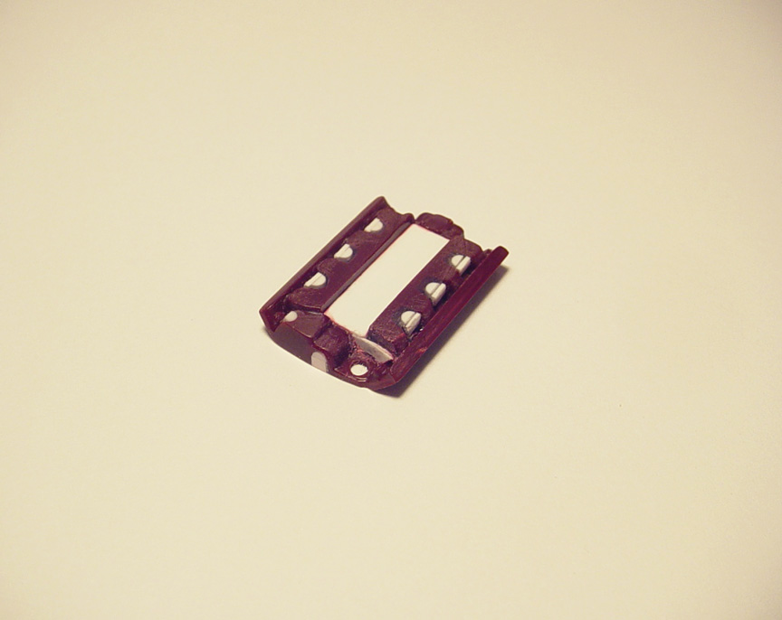
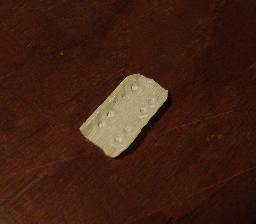 I decided the best place to start with was a manifold base from the AMT Chevy II Funny Car.
The throttle bodies and ribs were all ground down with a Dremel.
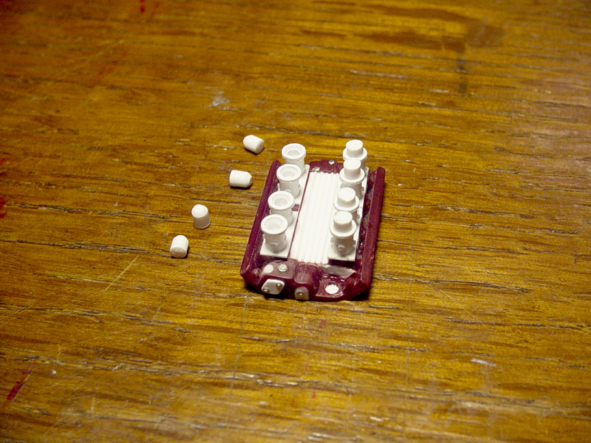
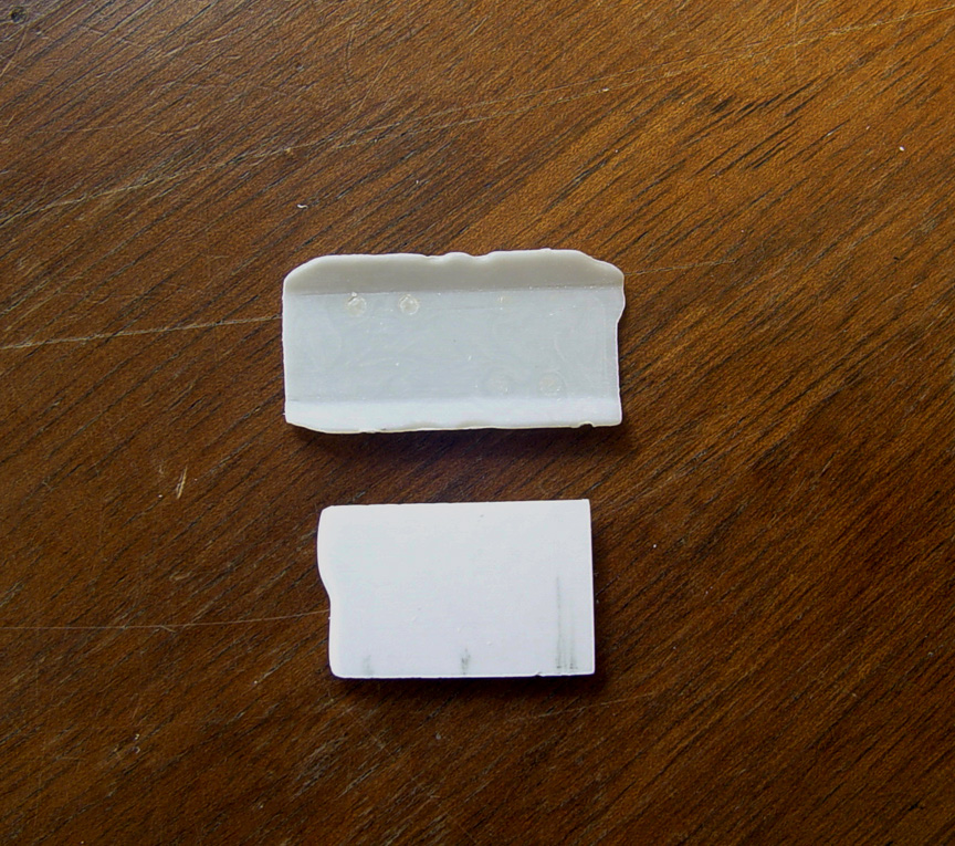 After smoothing out the manifold base, .080" plastic sheet was shaped and used to make the blower intake (below).
 .040" Plastic strips were needed to fill the sides of the blower intake.
 I cut a "BURST PLATE" from our Speed City Resin 426 Blower Manifold (upper right).
Also added some filler strips to the top of the "Burst Plate".
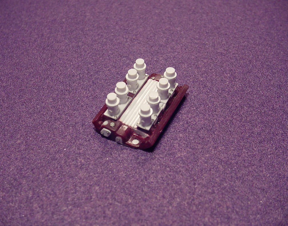
 Here's the new "Burst Plate" and some water line hook ups on the front.
 More water line hook ups on the rear and a molding for the location of the distributor.
I also added 2- Pro-Tech .020" bolt heads to the rear of the manifold (not in this photo).
12 separate parts make up this new BBC Blower Manifold.
MASTER IS FINISHED !

396 - 427
BIG BLOCK CHEVY ENGINE
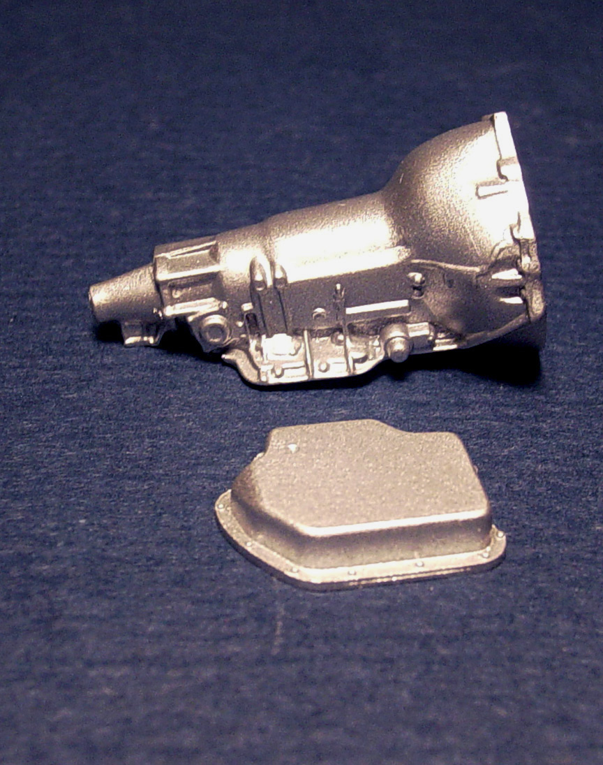
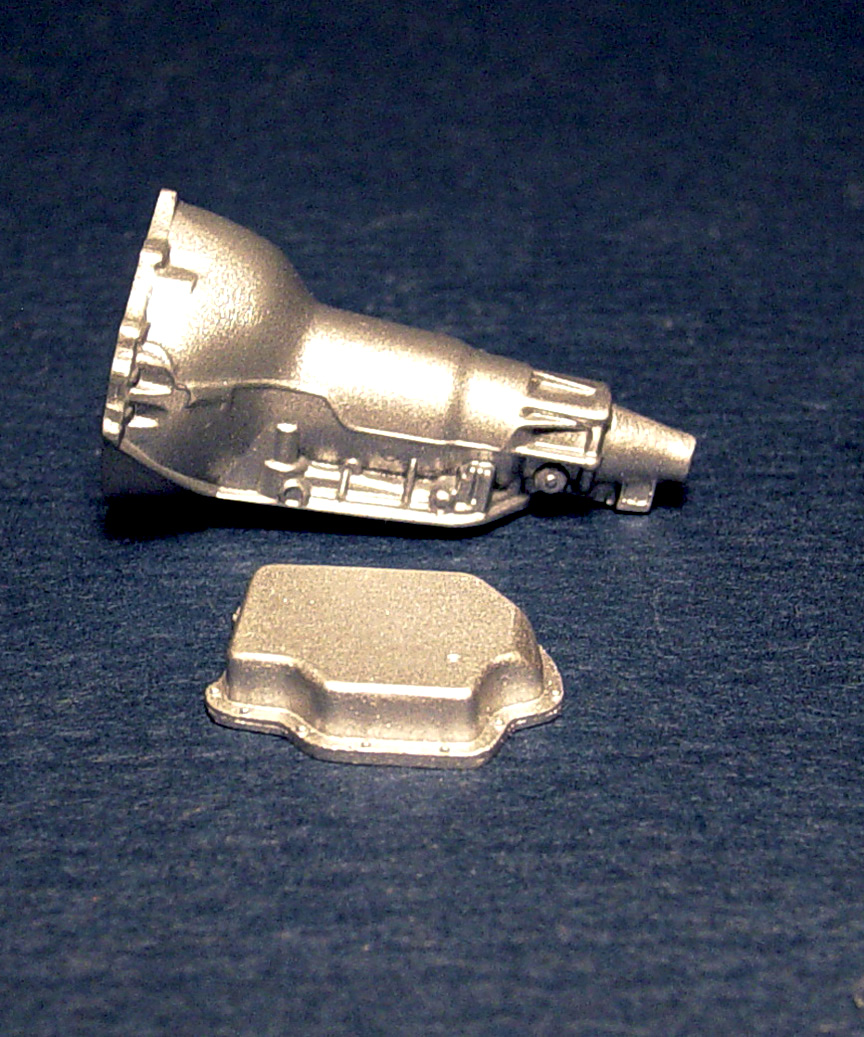
Since were doing a new BBC engine, we'll need a correct transmission to go with it.
Once again; we set out to create a correct one !
After a lengthy extensive search, we came up with nothing but incorrect transmissions from every G.M. kit we could find.... Except one.
That transmission was cut from the Cadillac engine block and a cap was made to make the tranny a solid piece.
MASTER IS FINISHED !

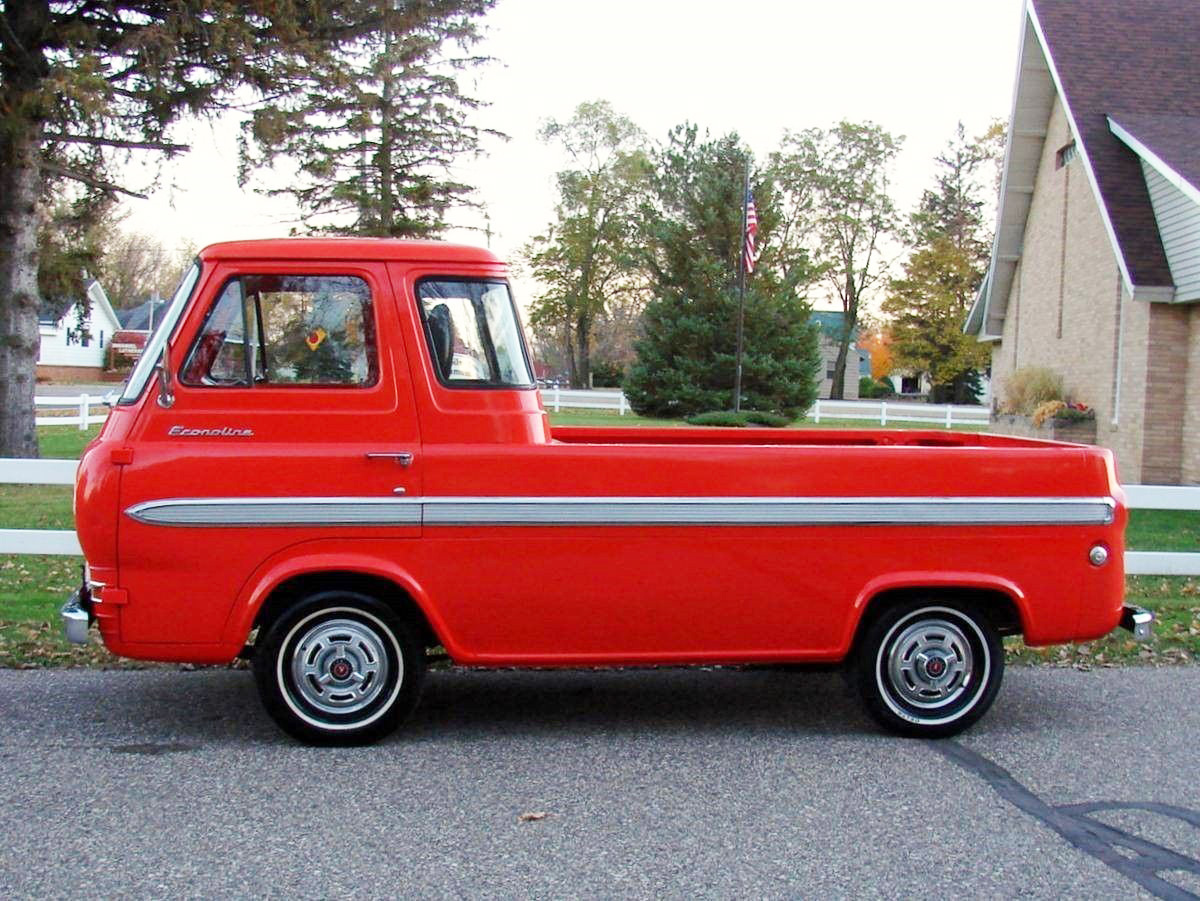
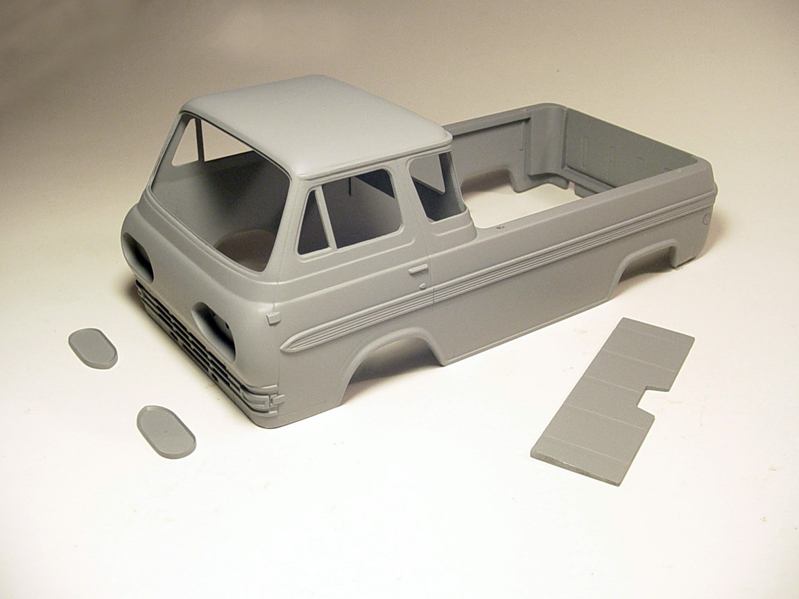
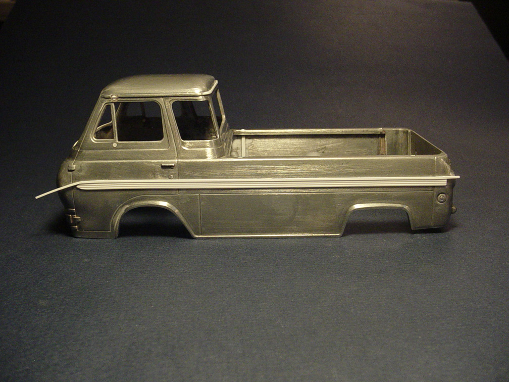
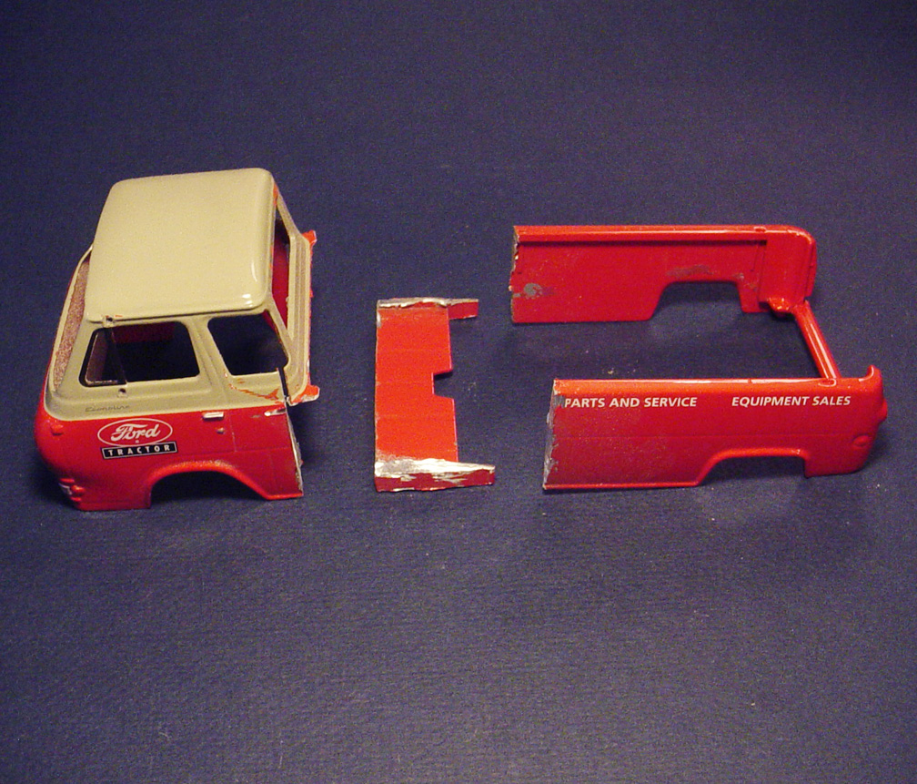
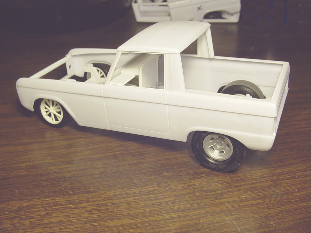
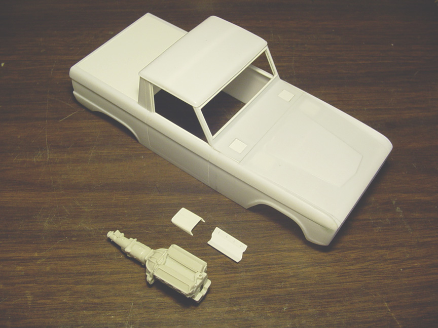
 The First Gear die cast model can not be built as a '65 Econoline, because it doesn't have the side molding (that only came on a '65 model) !
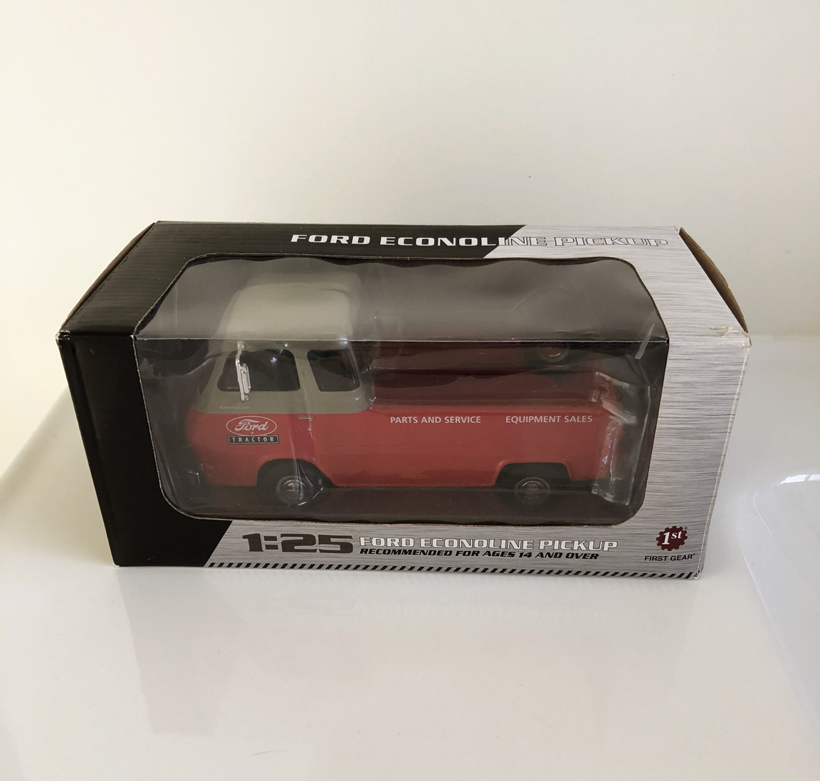
It will be nice to have this model in resin as the die cast body is extremely heavy.
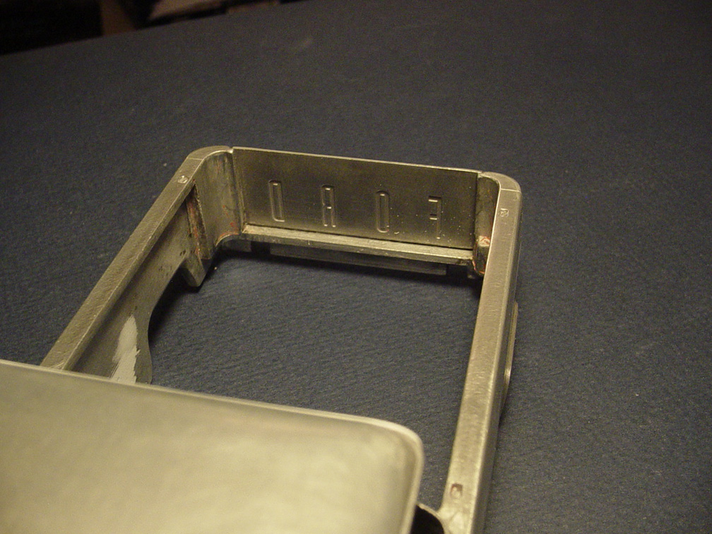
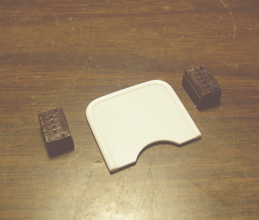
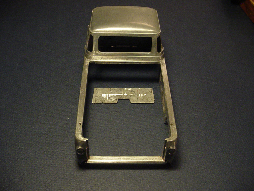 After spending 5 days trying to strip the paint (I believe it's powder coating), the "Cab Divider Plate" was cut from the body.
It will be easier to cast this body without the divider plate. But, I will need another die cast body to have a separate divider plate as this one will be trashed.
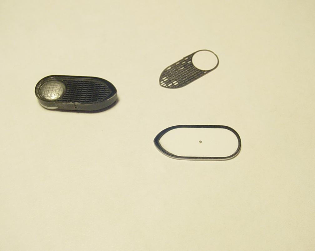
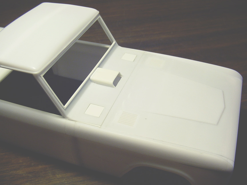
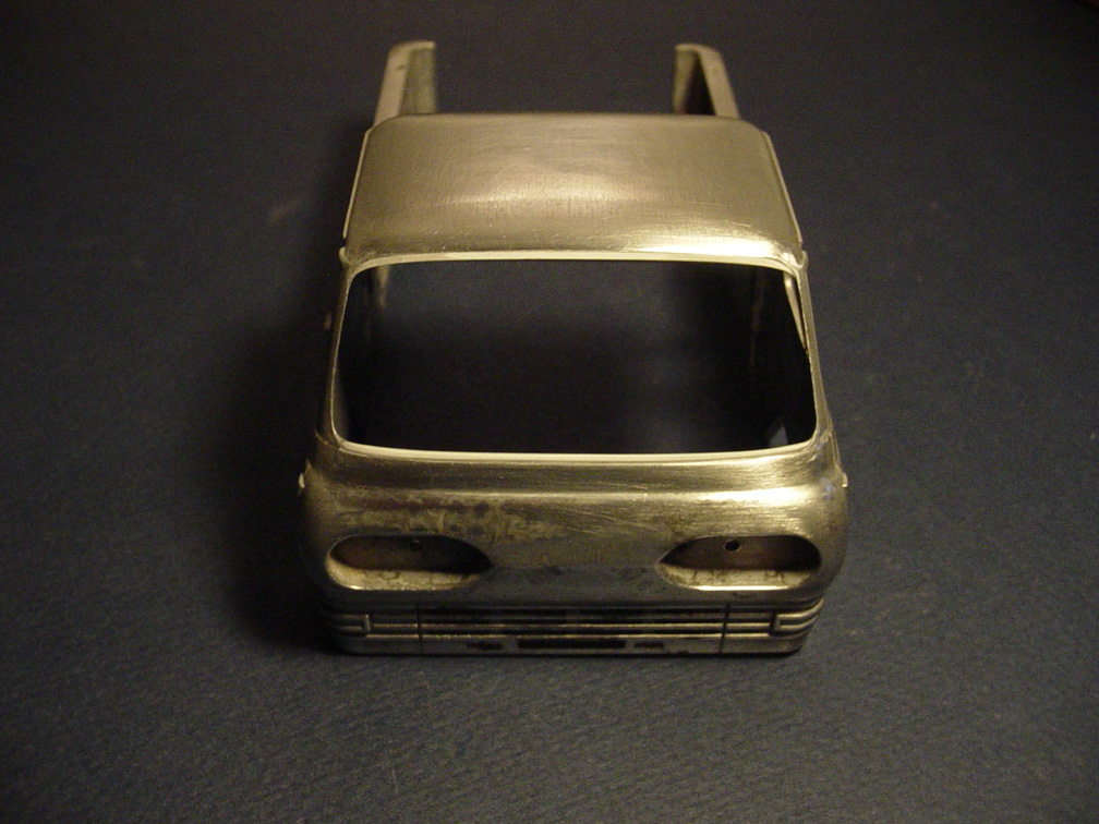 The biggest issue with the first gear die cast is the windshield... It's way over sized.
To fix this problem, plastic strip was added to the top and bottom and sanded to fit the body's contours.
 .010" Plastic sheet was added to the windshield area for the window recess.
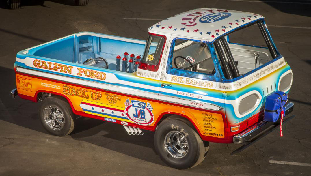
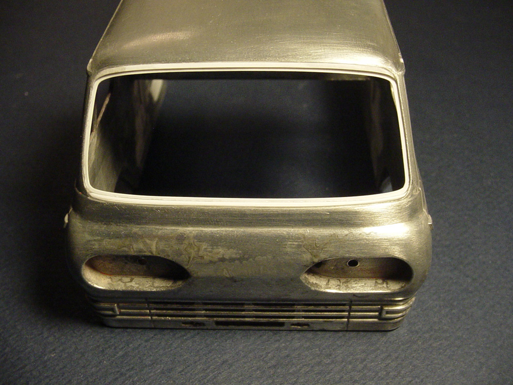 A window recess is necessary for the Back Up Pick Up Wheel Stander.
You'll need to remove this recess if using the First Gear windshield (for the stock version).
If you want the windshield to be correct for the stock version, you will need use plastic sheet for the windshield and
add black pin stripe tape for the weather striping.
Check out the "MODEL NEWS" page for instructions on how to make window glass.
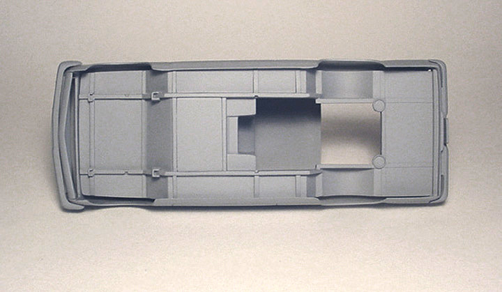
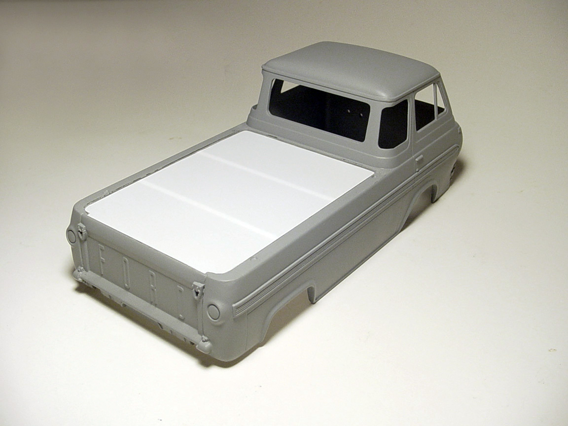
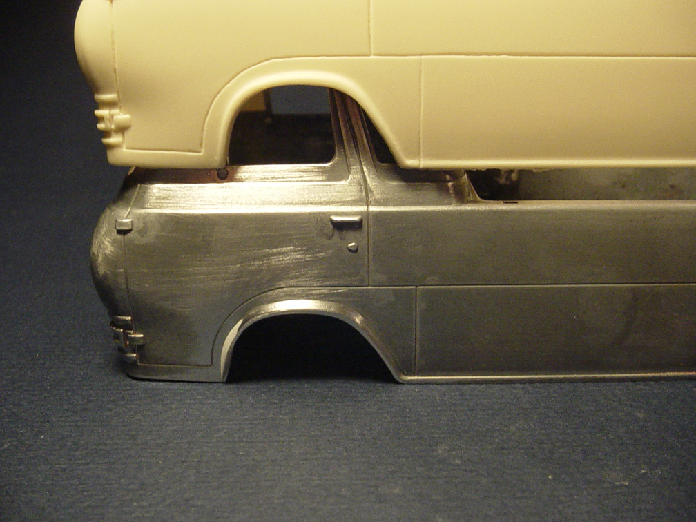 The front wheel wells are shaped incorrectly, so the front section was ground out and back filled with putty to make a new lip.
 There was no drip rail on the rear of the cab, so plastic strip was added.
The rear view mirror holes were filled and putty was added to the inside of body from grinding.
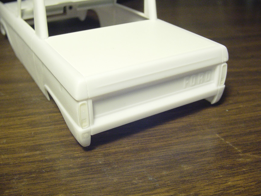
 The tailgate was glued in place and all spaces were back filled with super glue.
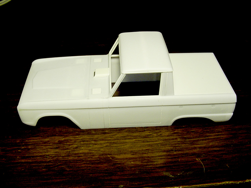
 Here's where it gets difficult and what will make this model be a '65 Econoline.
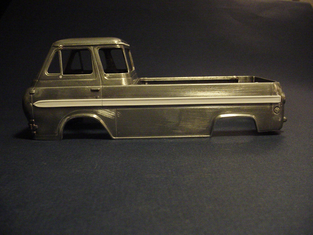
The center section of the side mouldings were created with H.O. scale siding plastic sheet, cut to size and sanded to perfection.
The H.O. siding is .040". It had to be sanded down to .020" thick.
Lines were scribed on the body to make these mouldings lay straight.
An engraver cutting tool was used on the body where the side mouldings are being mounted to (as plastic doesn't glue well to metal).
.030 strip is used for the chrome mouldings around the center section. This whole process took 5 days!
 All the edges on the chrome mouldings were slightly angled.
The door lines were also cut into he mouldings.
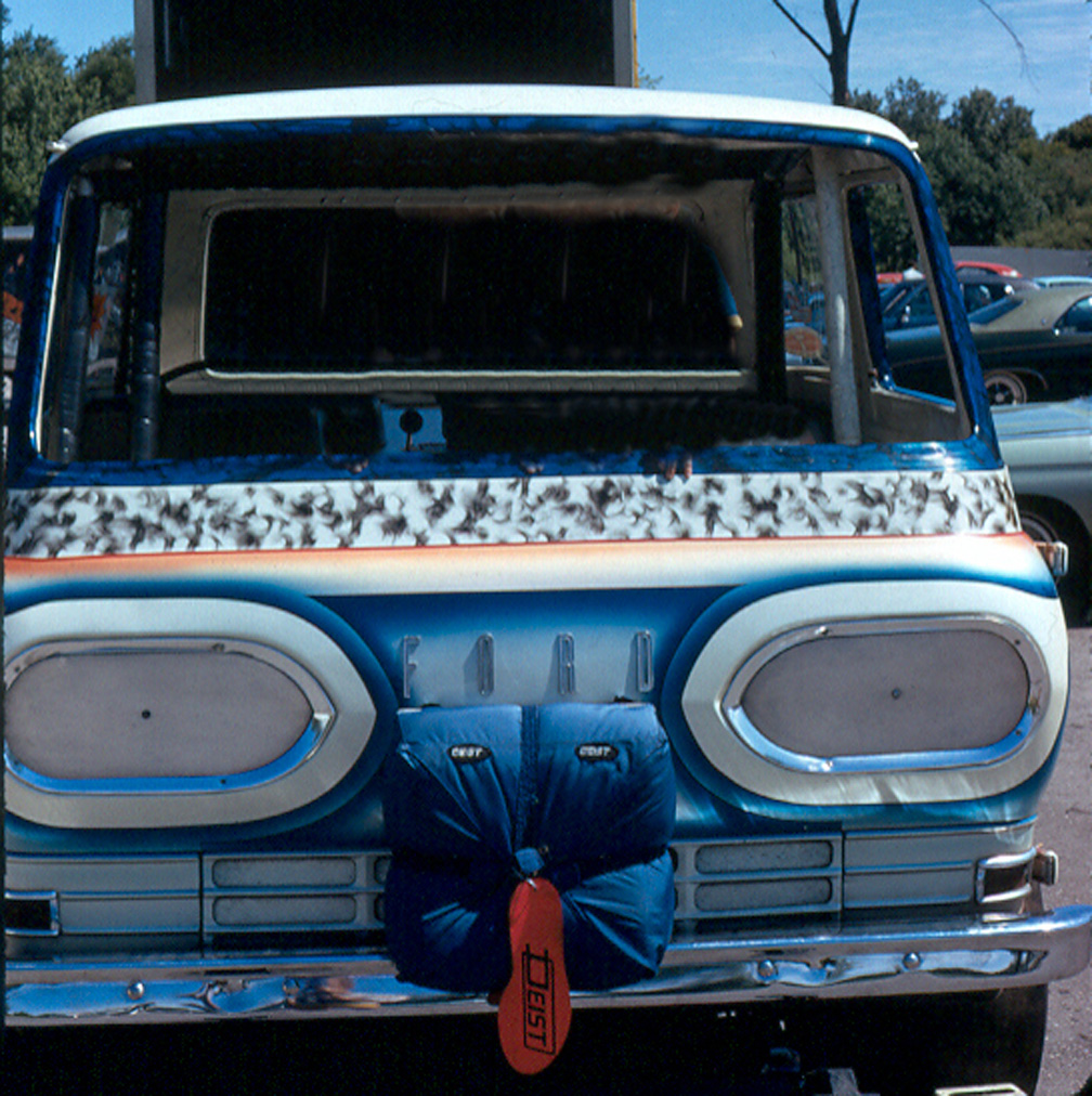
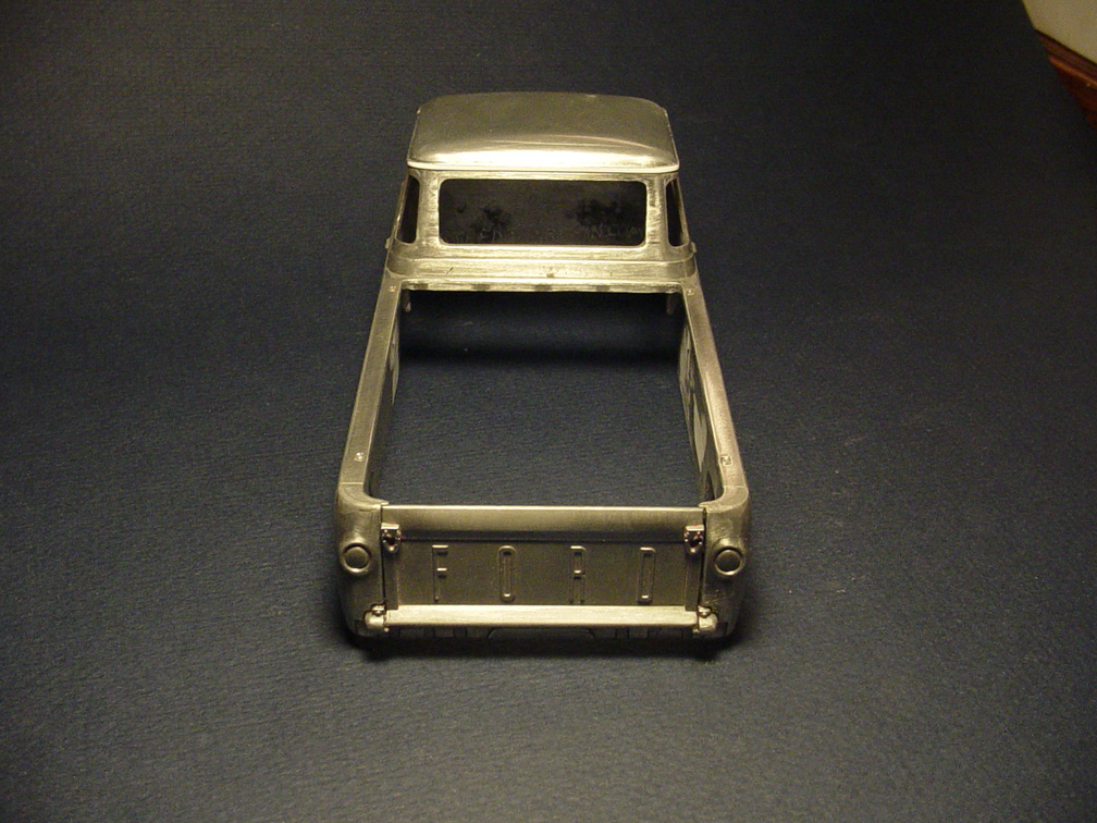
 The Back Up Pick Up doesn't have head lights, so block outs needed to be made.
The stock head lights will come in the First Gear Die Cast model that you will need for a donor kit.
 A good friend (Jim Polli) bought a First Gear Die Cast Econoline and sent me his metal body to work from,
as he will be using our resin '65 Econoline body when it's finished.
I'm going to make the "Divider Plate" (between the cab and bed) be a separate piece!
To get a good divider plate, I will need to trash the body.
After cutting out the Divider Plate from the body, the plate was stripped and the sides (left fron the body thickness) were ground away.
All imperfections were cleaned up and holes were all filled.
 A Bed Cover was added to ensure a better casting.
The Bed Cover can be scribed out using the back of a razor knife...... Or, it can be left on for a custom Tonneau Cover?
You will need a First Gear Die-Cast model as a donor kit for all the other parts needed.
Only the body on the First Gear model is Die Cast..... All other parts on there are plastic.
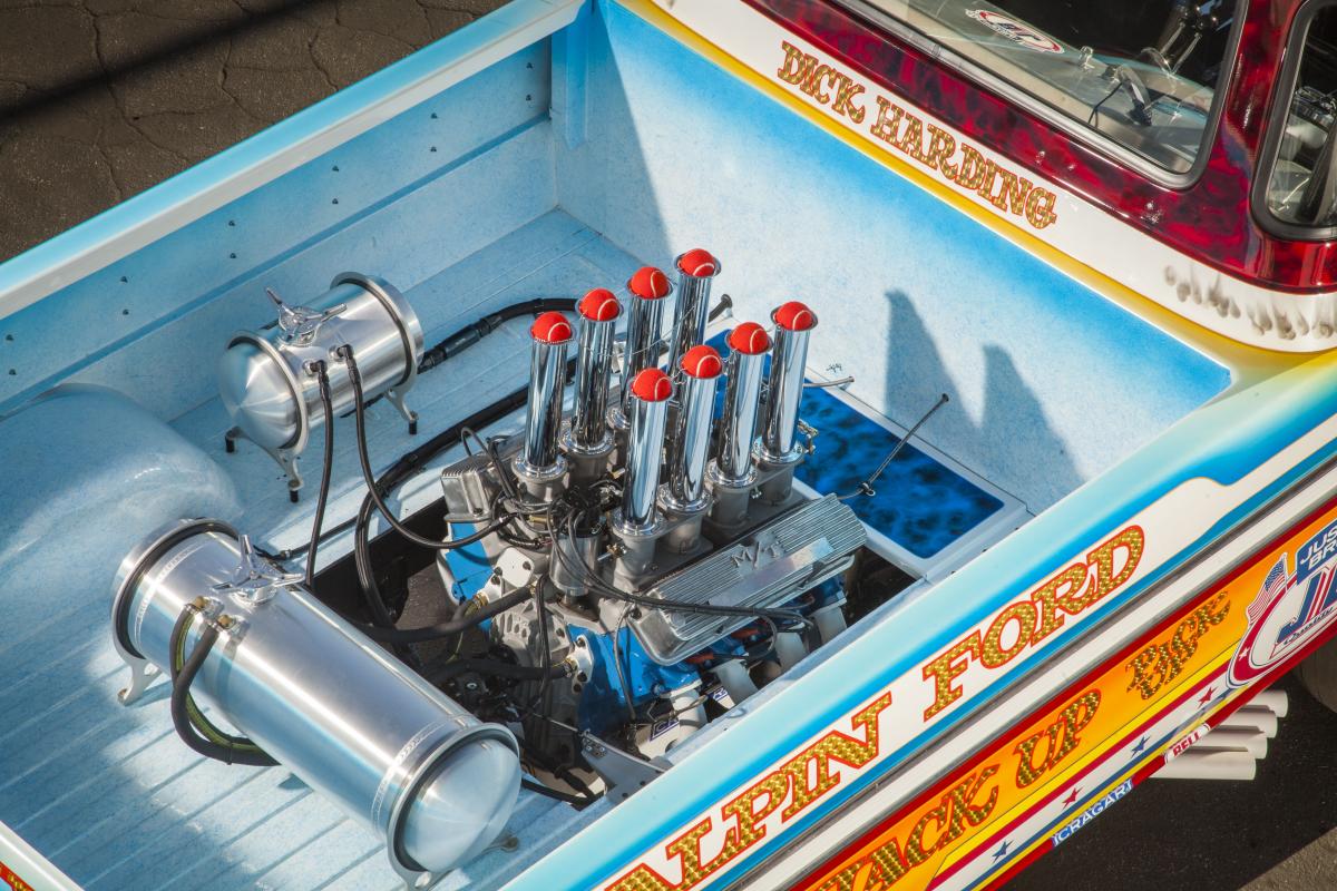
No model company ever made a Ford 427 fuel injection set up (or) Ford 427 M/T Valve Covers.
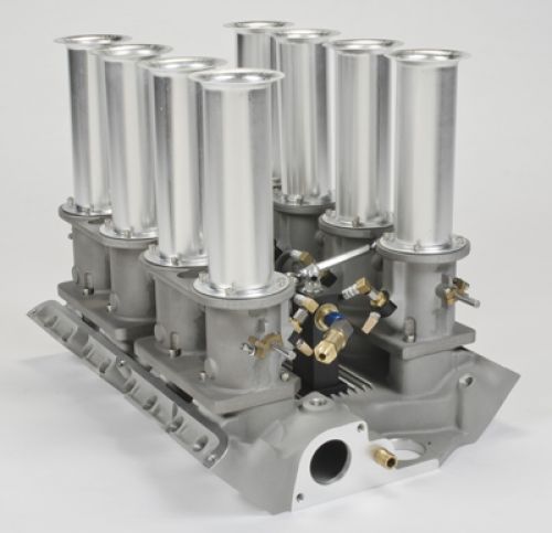 The plan is to replicate this 427 Injection Manifold in 1/25 scale.
 After reviewing all the Ford 427 intake manifolds, the best one to start this project is the Revell Ford Thunderbolt Intake Manifold.
After de-chroming the intake, it was sanded down to remove the carburetor platforms.
All the holes were filledand half round and flat strip was added between the intake tubes.
 4 throttle body plates were added. .080" hollow round tube is used for each throttle body.
Holes were drilled through each throttle body for fuel line plugs.
 Throttle bodies were drilled all the way through and .030" was used for the throttle rod plugs.
The top of each throttle body has mounting plates for the stacks to be mounted to. These were made by using a punch and .020" sheet plastic.
Cooling fins were added to the center of the manifold. Each mounting plate was then drilled to have .080" tube to be used as guides for the injection stacks.
6- Photo etch nuts & bolts were added to the manifold.
 16- .020"photo etch bolt heads were added to each mounting plate.
The hole in the bottom of the manifold was filled with putty.
It took 94 changes to the Thunderbolt intake to make this new Ford 427 Injection Manifold.
M/T FORD 427 VALVE COVERS
 Since no kit ever made M/T Ford 427 Valve Covers, I'll need to make these too.
To start this project, I'll be using our Speed City Resin "Big Block Chevy M/T Valve Covers".
Both sides were shortened. The top's and bottom's were also shortened.
The bottom lip with the bolt heads was removed and the valve cover was sanded down to make even smaller.
Since the bolt pattern is different on Ford Valve covers,
half round was used to back fill all the Chevy bolt hole indents.
The top plug between the fins were removed on both V. Covers and had to be back filled with ultra tiny pieces of plastic for the cooling fins.
All the lines between the fins were deepened.
 New bolt indents were filed out, to match a Ford bolt head pattern.
The valve covers were glued down to .020" sheet and .030" rod was used for the bolt heads.
 You can see the difference from the original BBC Valve Cover (on the bottom) compared to the new Ford 427 M/T Valve Covers (on the top).
TIMING COVER
 Using a Timing Cover from a Revell Ford 427 Parts Pak,
the left side was removed and a Fuel Pump Mounting Plate was made with .100" hollow tube and a .064" smaller round tube.
 Finally, 8 - photo etch bolt heads were added.
MASTER IS FINISHED !

FORD 427 WEDGE INJECTION
*PARTS PACK*


MASTER IS FINISHED !
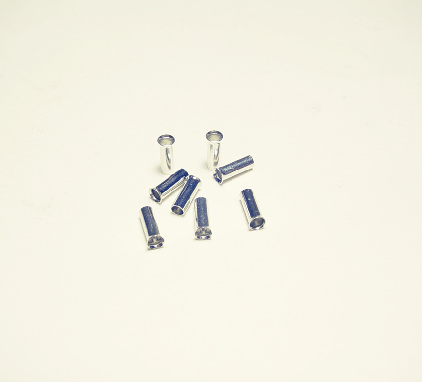
No aftermarket or model company has ever made 16" Cragar *Shallow Dish* Mag Wheels.
Since most drag cars ran 16" mag wheels, I'm going to create them in 1/25 scale.
Comes with S/S Cragar Center Caps and a mounting stub for an axle.
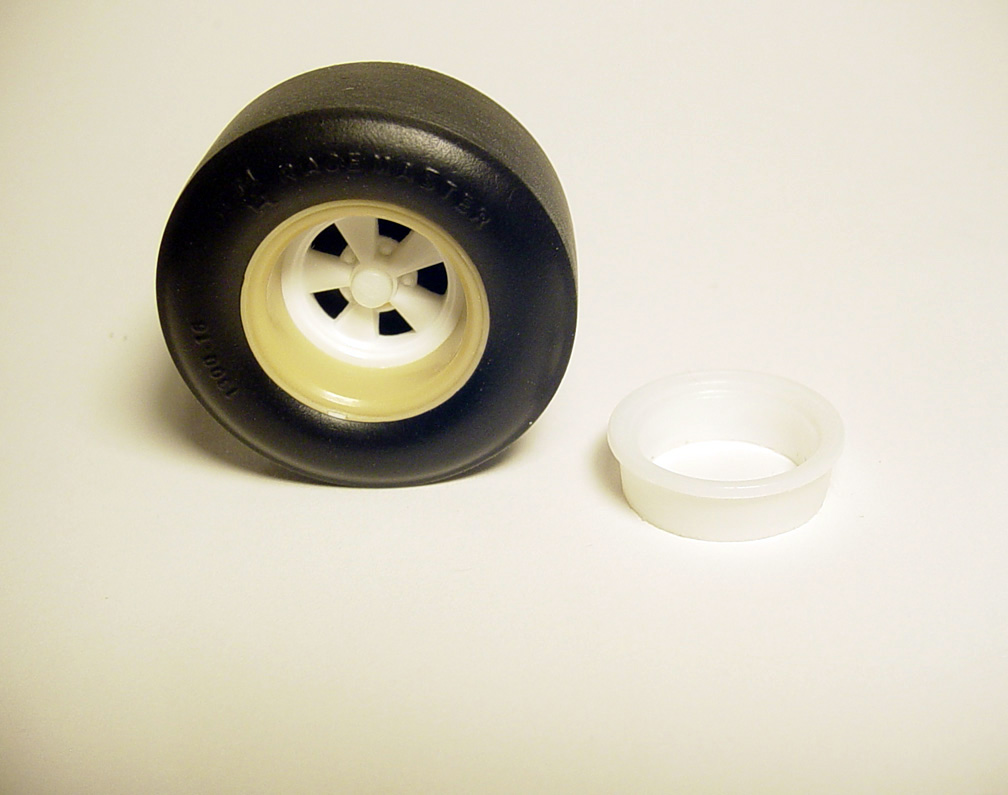
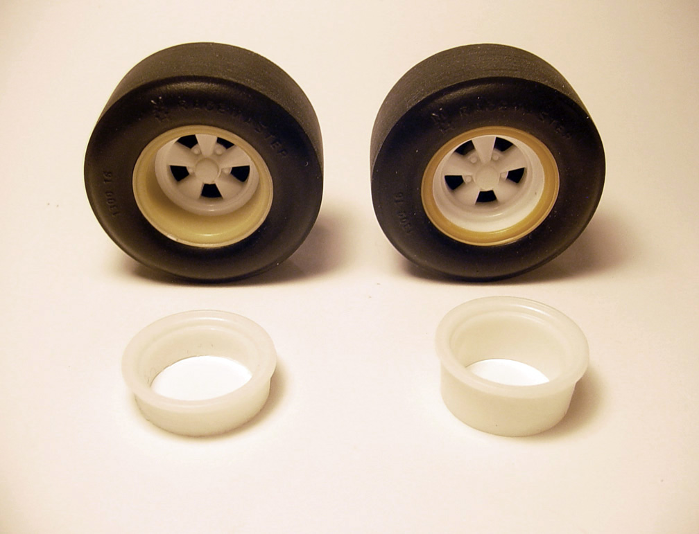
Our Speed City *Shallow Dish* "INNER RIMS" will be needed for these mags.


MASTER IS FINISHED !
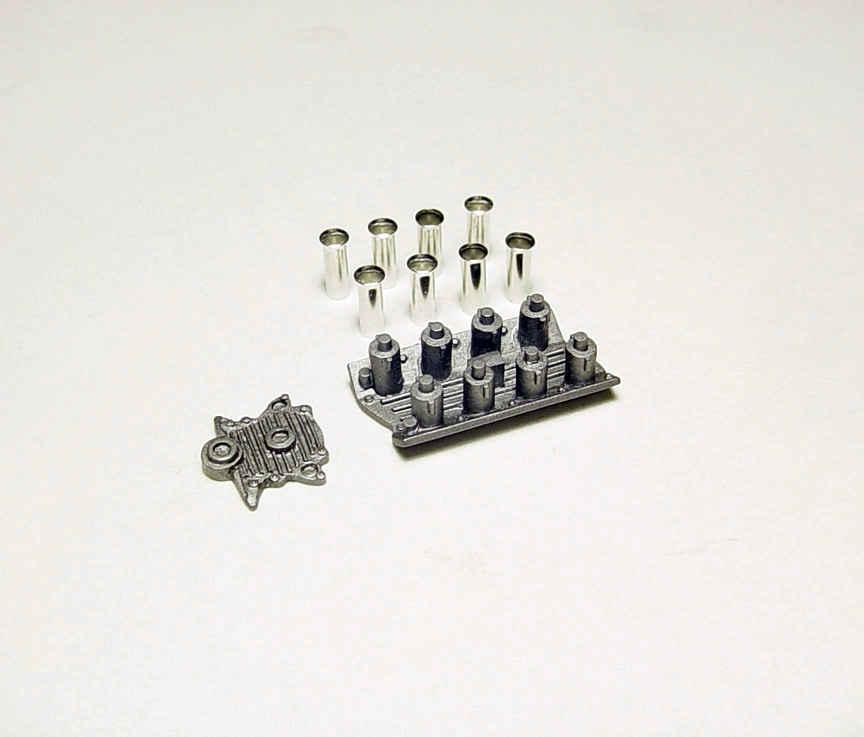
No aftermarket or model company has ever made 16" Cragar *Deep Dish* Mag Wheels.
Since most drag cars ran 16" mag wheels, I'm going to create them in 1/25 scale.
Comes with S/S Cragar Center Caps and a mounting stub for an axle.
Our Speed City *Deep Dish* "INNER RIMS" will be needed for these mags.
16" Cragars are shown here with the Inner Rims that can be used for the Deep & Shallow Dish.
 This new 426 Hemi project is being based on a "period correct" factory stock 1964-1971 Hemi Engine.
 Notice how far the block extends forward (for the timing chain and distributor).... You don't see that on any 1/25 scale Hemi engine.
That's why it's so hard to mount a distributor on almost every model kit Hemi.
 After much deliberation on which Hemi engine to start with?
The Revell 70's Funny Car- Block, Heads & Blower Manifold seems to have the best potential to make an accurate 426 Hemi.
The top, bottom and Transmission area's of the block were all filled with sheet plastic.
The Revell's front block protrusion was removed and a "Timing Cover" from our Speed City Resin "AFX PARTS PACK" was glued in place.
The "TIMING COVER" then had all it's face detail removed.
 I want the front of this new engine block to look as close to this photo as possible!
 To make all the Water Ports, several sizes of round and 1/2 round tube are used, along with making the Oil Filter port detail,
Distributor port detail and Water Inlet Cap (for radiator hose) on the side of the block protrusion.
 The frame rail mounts were cut off a Revell "Stone, Wood's & Cook" Willys Gasser frame to be used as new "Motor Mounts".
The holes were filled to resemble bolt heads.
Water Inlet "Block Off Plates" were added and water line protrusions on the front of the block were made from .030" 1/2 round tube.
A Transmission mount was cut from plastic sheet and 3 angled pieces were added to the top of the rear of the block (not shown in this photo).
12- Pro-Tech photo-etched Nuts & Bolt heads were applied, as well as an R-B Motion washer for the distributor location mount.
 The reason I started with the Speed City Resin "Timing Cover",
is that It fits the bolt pattern from the MPC Ramchargers Dragster Timing Cover; (that has been altered with round tubes), for the fuel pump and balancer.
 The block has had 48 alterations done to it at this point.
 The top's and bottom's of the heads were filled in. The sides were re-angled (to make sure it fits our Hemi Hilborn Injection Manifold).
Water port detail was added with 1/2 round tube. The weird V-shaped plugs on the (front and rear) of the Revell heads were drilled out, reshaped and
.040" plastic tube was inserted, and the top's were back-filled to make it resemble freeze plugs.
16 changes were made to make the heads to make it look more realistic.
 Here's the Revell Funny Car Blower Manifold.
It's too narrow to fit the re-shaped heads and needs to be made solid for casting. But it does have a "Burst Plate" & Springs.
 The manifold's top, bottom, front and sides were all filled with plastic sheet.
The top of the manifold needed to have an extra strip of plastic to bring it out farther to fit the blower.
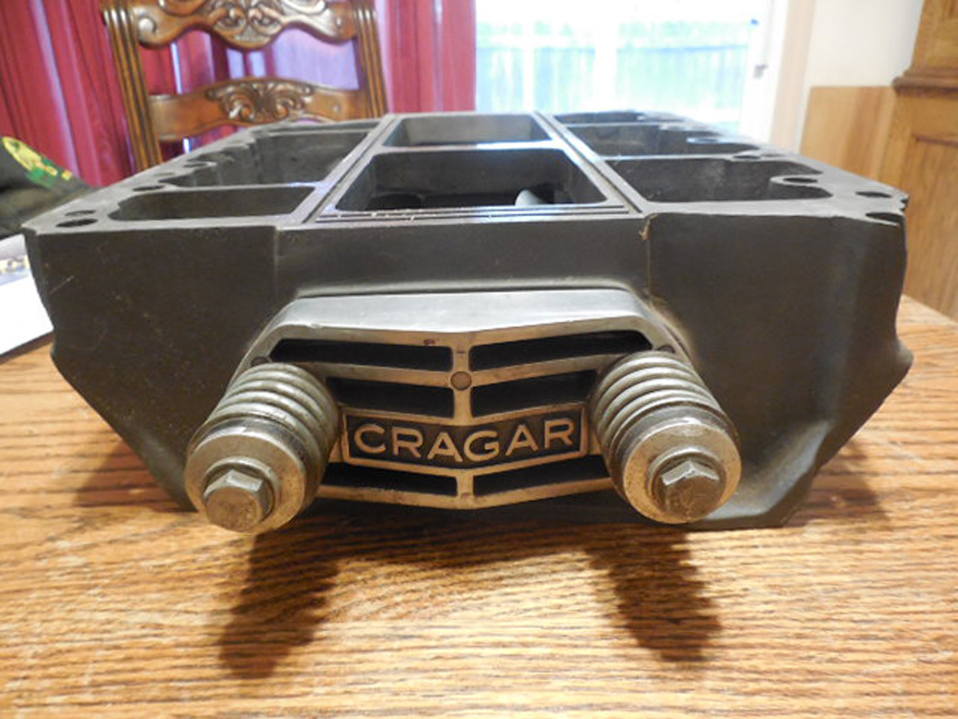
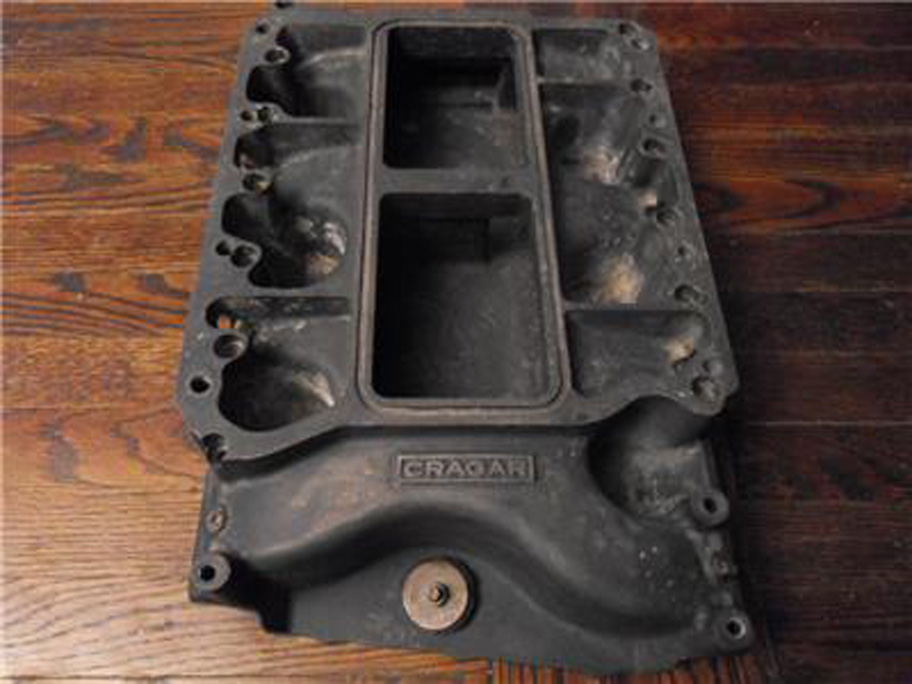 I'm going to try to make this manifold resemble this vintage 426 Cragar Blower Manifold with a correct "Burst Plate".
 Even though the Revell manifold came with a Burst Plate (with springs),
I found that the 1320 die cast dragster had a much more detailed Burst Plate and it looked very close to the 1:1 Cragar Burst Plate.
So, the die cast dragster was pulled apart and the Burst Plate was removed and grafted to the new manifold.
Extra detail was added with plastic strip & round tube and was then topped off with a photo-etch Bolt Head.
14 extra parts were used to create this new Cragar Blower Manifold and
5 days were spent making it.
 Rear of the block- Here you see the 3 angled pieces that were added to the top rear of the block.
After this photo was taken I realized that the block wasn't long enough for the right side of head, so it was lengthened with plastic sheet.
 A Little Red Wagon 426 Hemi Oil Pan needed a sink hole filled and will be added to the mix.
After 63 modifications, all parts fit perfectly.

The 426 Hemi Engine Master is finished !
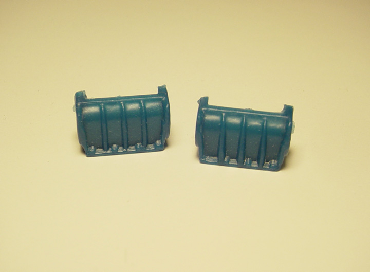 The most accurate "Blower Case" is in the Revell "Miss Deal" Funny Car & the Revell Stone, Woods & Cook Willys Gasser.
It
seems to have the right size and shape.
But, I've noticed that the right side of the Revell blower case is always messed up (shown on the right side).
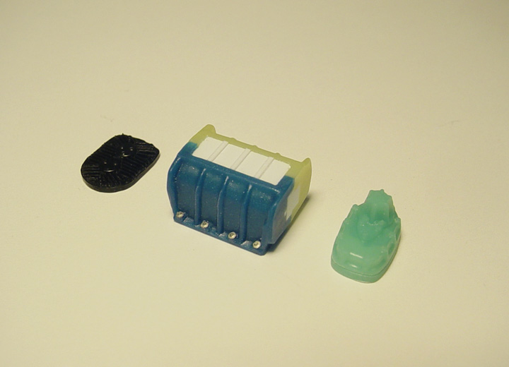 I found another Revell Blower Block (yellow) and the two left sides were meshed together to make a better solid block.
I capped off all the holes and added some top ribs for the intake using .010 x .020" strip.
There is no Bolt detail on the Revell Blower case sides, so photo-etch Bolt Heads were added.
The rear Bearing Plate is from my parts box as it had the best detail.
The front Drive Plate back side was filled in with putty and a separation line was scribed in around the plate.
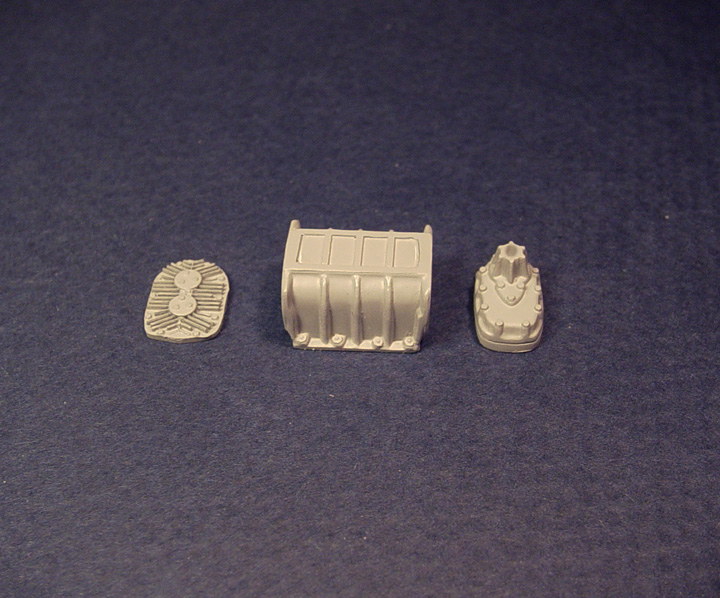
MASTER IS FINISHED !
After careful deliberation on which body to start with,
it was decided to start this project with our '67-'68 Barracuda Funny Car resin body.
Since this body has already been perfected including, removing all body trim, emblems, wiper blades,
filled cowl vents, corrected front & rear valance's, window chrome trim removed, window recess' installed
and the entire body sanded & polished to perfection....... It should be a great candidate to start with.
(To see all the work that was done to the '67-'68 Barracuda Funny Car, visit the "IN PROGRESS" page 3)
BODY WORK
Started 10/10/2016
 The front wheel wells need to be in stock location and our '67-68 Barracuda F/C resin body has altered front
wheel wells. To get the front wheel wells back to stock position, an MPC '69 Barracuda body was used.... since I'm out of
spare resin '68 Cuda bodies.
 Here's the new stock Barracuda front wheel wells.
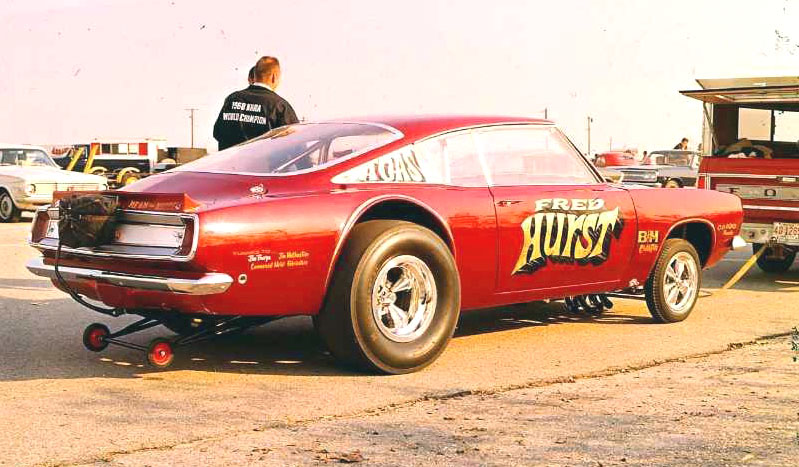
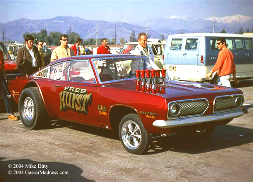
The Fred Hurst Barracuda had a fiber glass front clip, so the chrome moldings were removed.
 To make the radiused wheel wells....
Our Speed City M&H Racemaster 16" slicks were used as a guide to figure out the correct radius.
The wheel wells needed to be bigger than normal because there needs to be a plastic strip to create an even lip & inner surface for the fender flares.
030" plastic sheet was used. A round tube was used for sanding the circumference and to keep the wheel wells aligned evenly.
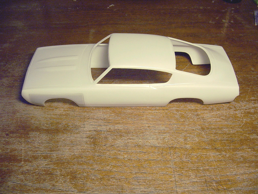
 Our '67-'68 Barracuda Fastback Funny Car body has filled in hood louvers and the Fred Hurst Gasser
needs to have slightly counter sunk stock louvers.
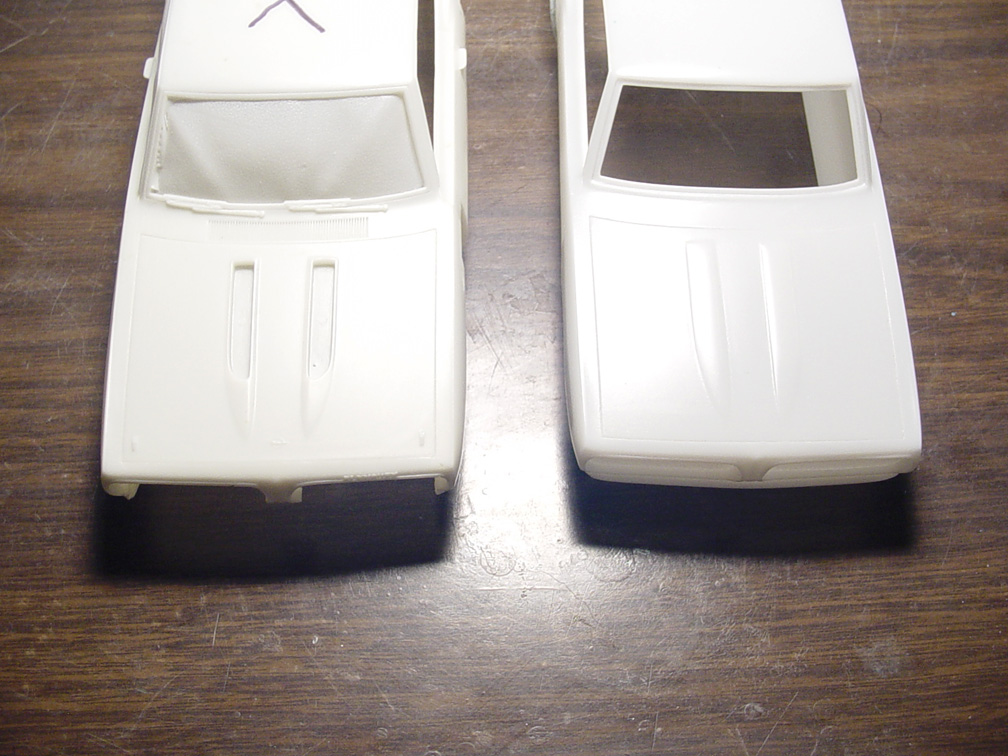
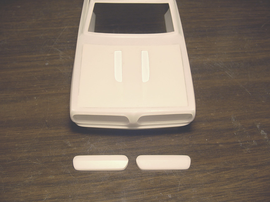
 Using our '68 stock Barracuda resin body (no longer in production), the hood was cut out.
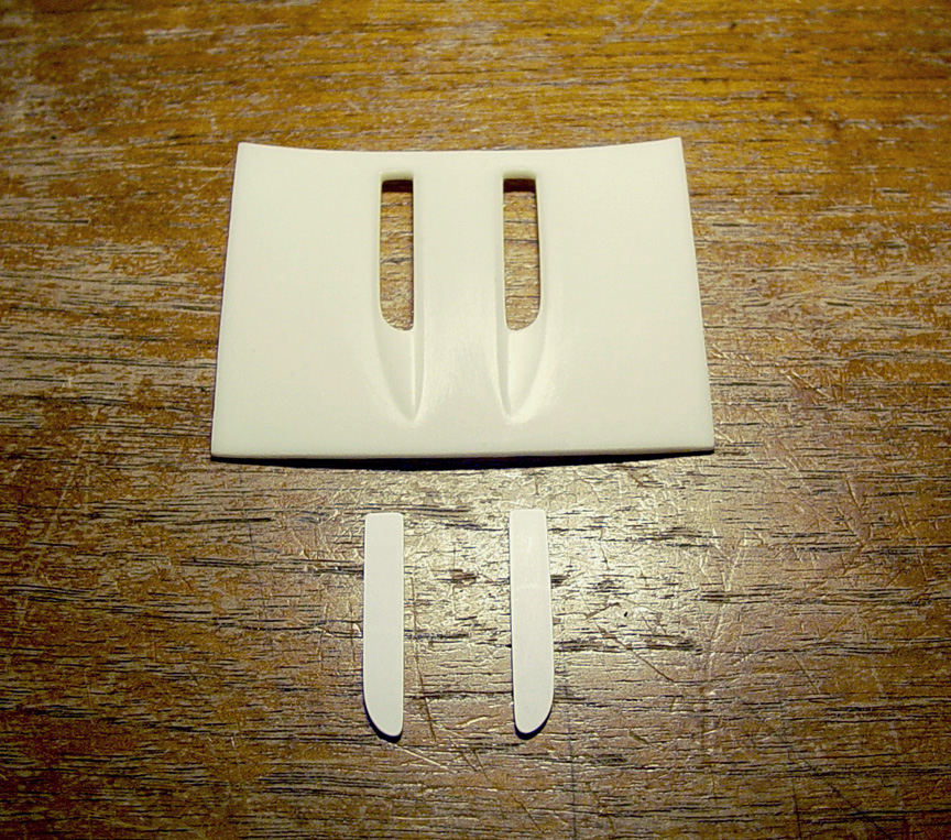 The hood was then thinned evenly and the bottoms of the hood louvers were removed,
then 2 pieces of .020" plastic sheet was cut to perfectly fit the louver holes.
 The new stock hood was glued to the Funny Car body and now has better looking louver bottoms.
The hood lines needed to be re cut into the Super Glue. You can also see the new rear fender flares in this photo.
 The rear spoiler from the "Speed City '67-'68 Barracuda Funny Car resin kit" was glued on
and molded to the trunk using a thin application of "Super Thin" Super Glue.
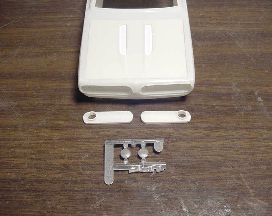
 The Speed City Resin '67-'68 Barracuda Funny Car body has no marker lights and the Fred Hurst Gasser
has them. After looking at a '68 stock Barracuda Fastback marker lights, it was decided to make new ones from scratch,
since the stock marker lights were so faint, they would most likely disappear after primer & paint.
Plastruct 3/32" Hollow Tube was used to make the marker light chrome ring bezels.
 .047" round tube is used to make the marker light red lenses.
 Marker lights finished and primer was used on the wheel wells to seal the putty.
 The body needed to have a A-Pillar window molding, so .020 X .040" plastic strip was used.
Now that the body is close to being finished, I'm moving on to the interior tub and chassis.
 The new front clip was prescribed to have correct hood lines and hood was pre cut for the injection stacks.
I'm keeping the body as a 1-piece body, so you will need to scribe out the front clip if you want to build a version with a
flip front end. I don't want to make the body & front clip separate because of this.... If we cast these 2 pieces separately,
the body & clip will not line up correctly due to the fact of using rubber molds, and the body will drift from it's original position.
Once you scribe the front clip from the body, they will have a perfect fit !
 Finally, our signature "semi-hollow door handles" are added.
The center of the handles can be poked through with a hobby knife to make them hollow.
GRILLS & BUMPER
Since the front clip was fiber glass, there were no grills.
Instead, it had smooth fiber glass block outs and then painted to look like grill mesh.
To be legal in the gasser class, the car had to have head lights. The grill mesh will need to be made in decal form.
Whoopie Kat will be making the decals for this car.
 Thankfully, I already made the grill block outs from our Speed City '67-68 Barracuda Funny car,
but the block outs had to have .010" strip glued all around the sides for a closer fit and very little putty will be used.
 I had no luck finding head lights that would fit the Barracuda grill block outs correctly,
so I'm using 1/4" tube for the bezels. The tube still had to be hollowed out more to create a thinner lip on the head light bezels.
The tube was also made to be a pressure fit so no gaps will be seen between the bezel and grill...... Extremely time consuming !
 Here's the block outs with bezels installed and the new head light covers that will be going in.
The backs of the head lights were primed
to see better when installing and they had to be made to be smaller in diameter.
 Head lights put in and final grill block outs installed using 5 min. epoxy, so they could be adjusted properly.
Glazing putty was used around the seams between the grills
The bumper molding on the body was sanded down to make the front bumper come closer to the body.
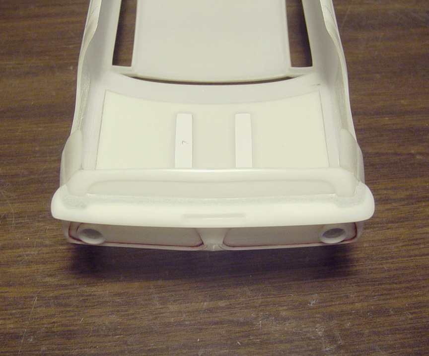 The bottom of the bumper was puttied in around the front valance.
INTERIOR TUB
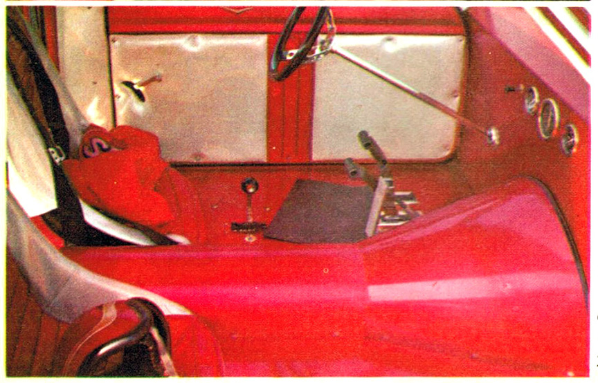 This Fred Hurst '67 Barracuda interior shot shows that the door panels will need to be custom made
as
This Fred Hurst '67 Barracuda interior shot shows that the door panels will need to be custom made
as
nothing even comes close to this. There's a lot of padding and "tuck 'n' roll" on this interior tub.
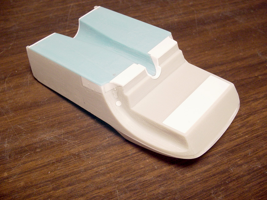
 Starting with an MPC '69 Barracuda interior tub, the tub needed to be corrected as it didn't seat to the
body right. Plastic sheet and putty was used to create a more rounded effect in the trunk area.
The holes (for the roll bars) were also filled.
 The floor was cut out and the trunk was filled in to create a flat surface, this will help for the new chassis design.
The
bottom of the wheel well humps and missing door panels were back filled with sheet plastic.
The door panel detail was all removed. Door lines were marked on the outside of the interior tub.
 The best contender I could find for a floor pan/ transmission tunnel is the MPC Malco Mustang Gasser.
 To make the rear part of the padding with the "tuck 'n' roll" center, plastic sheet was drawn and cut,
then the sides were sanded down to make it look like rounded padding.
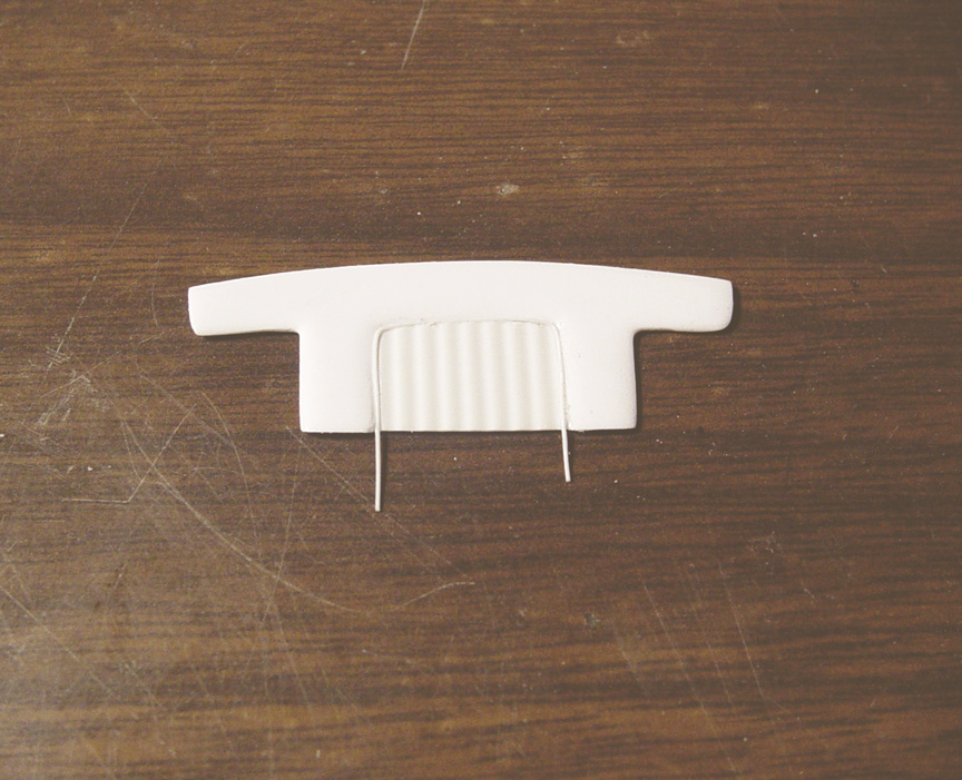 Rail road scale siding was reversed and used as tuck 'n' roll for the middle insert.
.010" tube was then added to simulate piping.
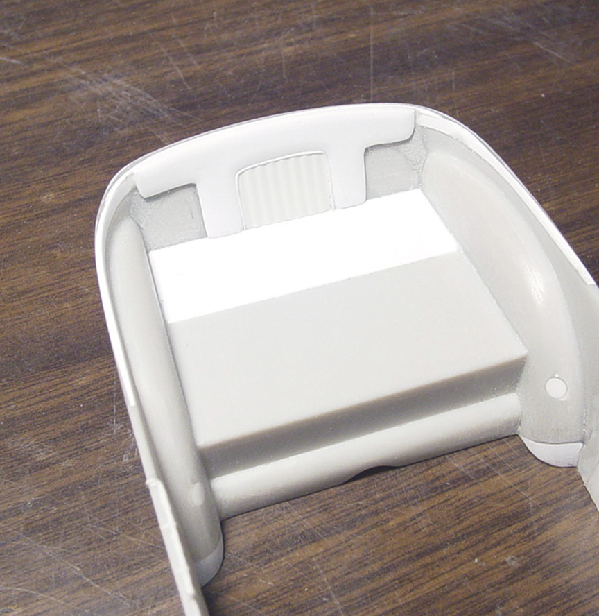 Here is the finished padding with "tuck 'n' roll" piece installed in the trunk area.
 Extra pieces were needed to lengthen the Malco Mustang interior floor and transmission tunnel.
 A new firewall and angled cowl was made to fit using sheet plastic.
The firewall & cowl was the trickiest part to do on this interior tub, since it had to fit perfectly to the inside of the body.
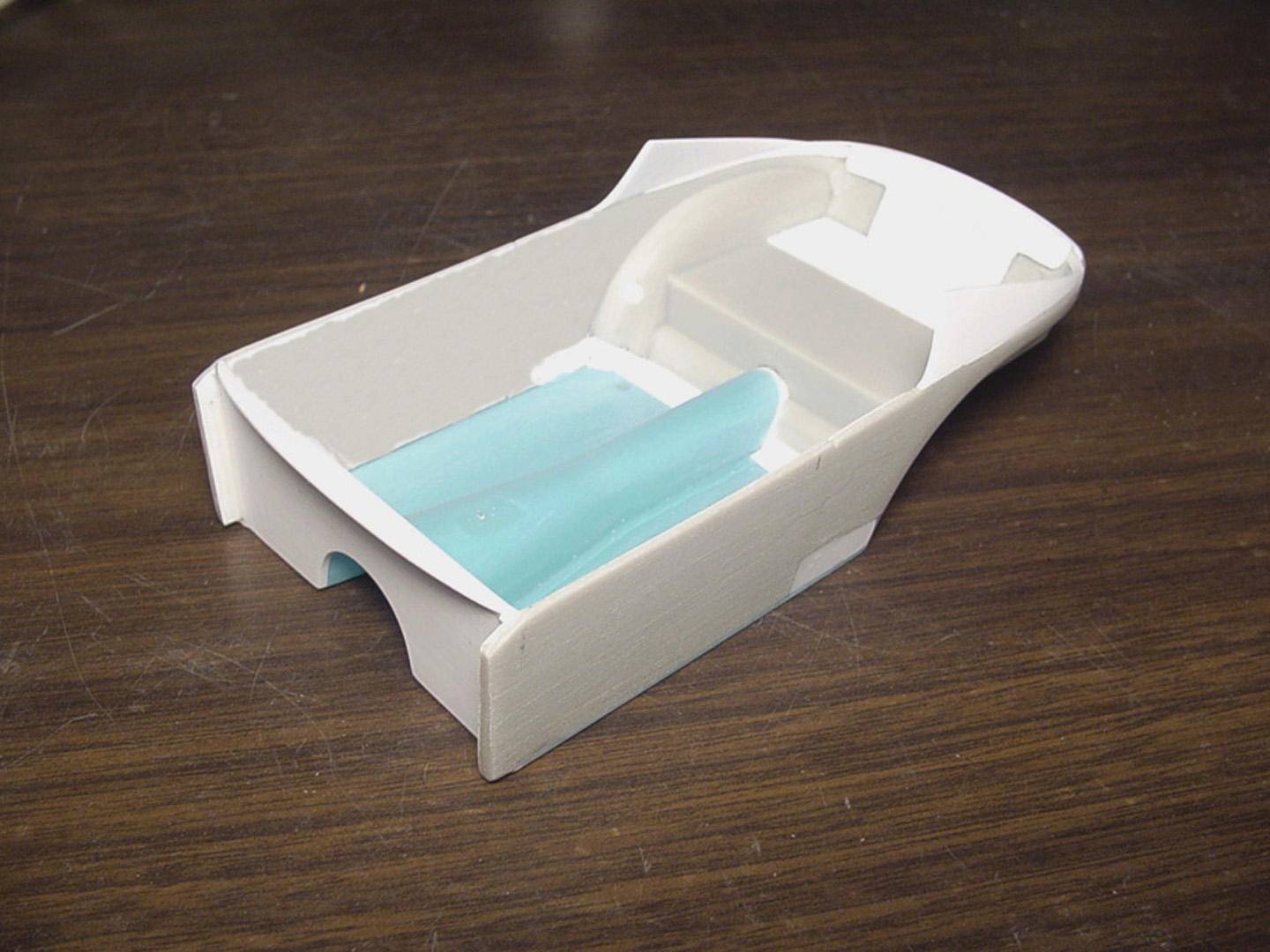
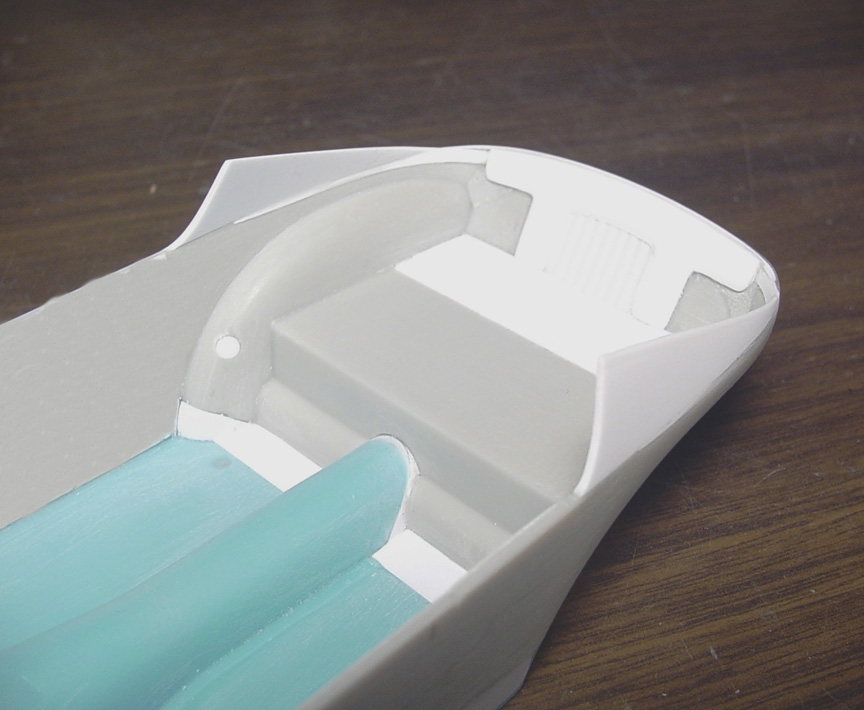 The padded sail panel inserts were formed to fit the inside of the body.
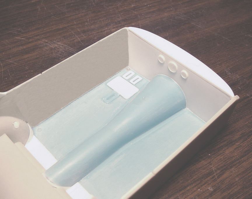 The B&M shifter box cover, brake & clutch pedal plates and floor mat were added to the floor.
The oil pressure, tach and water gauges were cut from parts box items and sanded down to scale so only the lip of the
gauges will show and then mounted to the firewall.
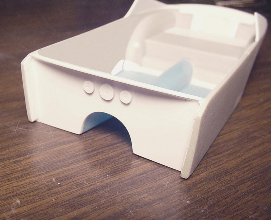 The backs of the 3 gauges were made from 2 sizes of punched out sheet plastic and pre-drill for lines,
then mounted to the front of the firewall.
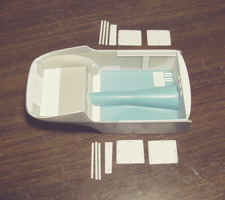 To start the door panels, the top of the interior door was made with 2 different size strips of sheet plastic.
.060" 1/2 round tubes were glued to the middle of the door to make the tuck 'n' roll padding.
4 pieces of sheet plastic were individually cut & shaped for each section.
To make it look like the buttons that are pulling the padding in, it was counter sunk for each button hole.
.020" bolt heads from Pro-Tech was glued to the center of each counter sink, then polished to be a round head.
A divider padding (behind the door) was cut to shape and the other 3 pieces of tuck 'n' roll 1/2 round are ready to be added.
 Finally, a steering column bracket was added and a hole for the steering rod was pre drilled in the firewall.
CHASSIS
 Starting with a Revell Stone, Woods & Cook Willys chassis......
The rear of the frame needs to be kicked up (to lower the car).
So, the rear of the frame was cut off and .080 X .156" strip was used to make the new Z' ed frame rails.
The middle frame cross member with rear shock mounts, was cut from the Revell frame & relocated higher on the new frame.
A strip of plastic was then glued to the front of the chassis to hold the distance between frame rails before cutting off the
radiator and fuel tank mounts.
 The radiator and fuel tank mounts were
re-designed and re- located.
The radiator and fuel tank mounts were
re-designed and re- located.
Many other unnecessary details and holes were either removed or filled.
I need to simplify the frame rails (for casting purpose's) so that the top of the rails are smooth with no disturbing details,
for better results in the molding process.
 Here's how the new frame rails will fit on the interior tub.
Surprisingly, the motor mounts are in the correct area and will not need to be relocated.
I put a frame cross member half way to the end of the interior tub so, when you add a trunk floor, you won't see the seam.
You can also add sheet plastic to the sides of the interior tub to seal in the trunk area.
The Revell "Stone, Woods & Cook Willys" suspension parts, engine & tranny can still be used as the donor model.
WHEELIE WHEELS
 After an extensive search trying to find small wheels to look like these (see photo).
I gave up and decided that they would also need to be hand made.
 I found some headlight bezels in my parts bin and altered them to look like wheelie wheels.
Finished 4/28/2017
Master is finished !
Since this Fred Hurst Barracuda needs front Torque Thrust Spindle Mount Mag Wheels,
I'll be creating those too, along with our signature Inner Rims.
This will be an all new accurate master !
Johan made an attempt at doing Spindle Mount mags and they're okay,
but there is no center cap on them, the spokes don't have the correct shape
and there is no axle hub, (which makes it even harder to use on different axles).
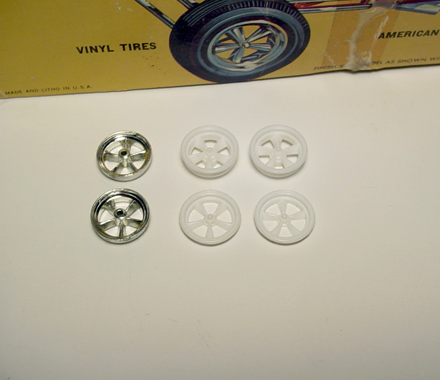
1. (On the left) The Polar Lights F/C attempt at making Torque Thrust "Spindle Mounts", but again, they're not shaped right.
Also, the spokes are too thick and they have a gritty rough texture to them. I can't see using these on any build !
2. (On top) The rare AMT "Cougar Country" 777 Funny Car has some better looking Torque Thrust "Spindle Mounts",
but the spokes are too thick and the Axle Hub is too big in diameter.
They just don't look like Gasser/Funny Car "Spindle Mounts", but would be better suited for street machine wheels.
It looks like AMT tried to make the mags deeper to fit the over sized funny car tires in the kit.
3. (Bottom) I used a second set of AMT Cougar Country F/C mag wheels I had and cut the axle hub off the back and sanded
down the back side of the mags..... This in turn, made the spokes skinnier and thinner.
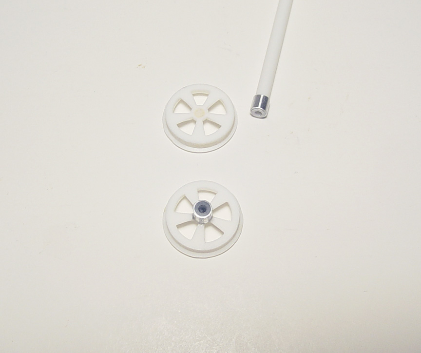 Since the new axle hubs will be smaller than any other standard axle hub,
I had to use an aluminum tube and a hollow plastic tube inserted into the aluminum tube to fit a metal axle.
But, that hole can be bored out if necessary.
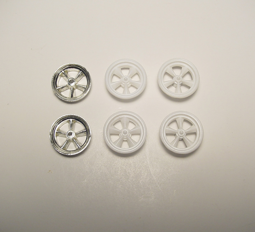 You can clearly see the difference between the three (ours on the right side).
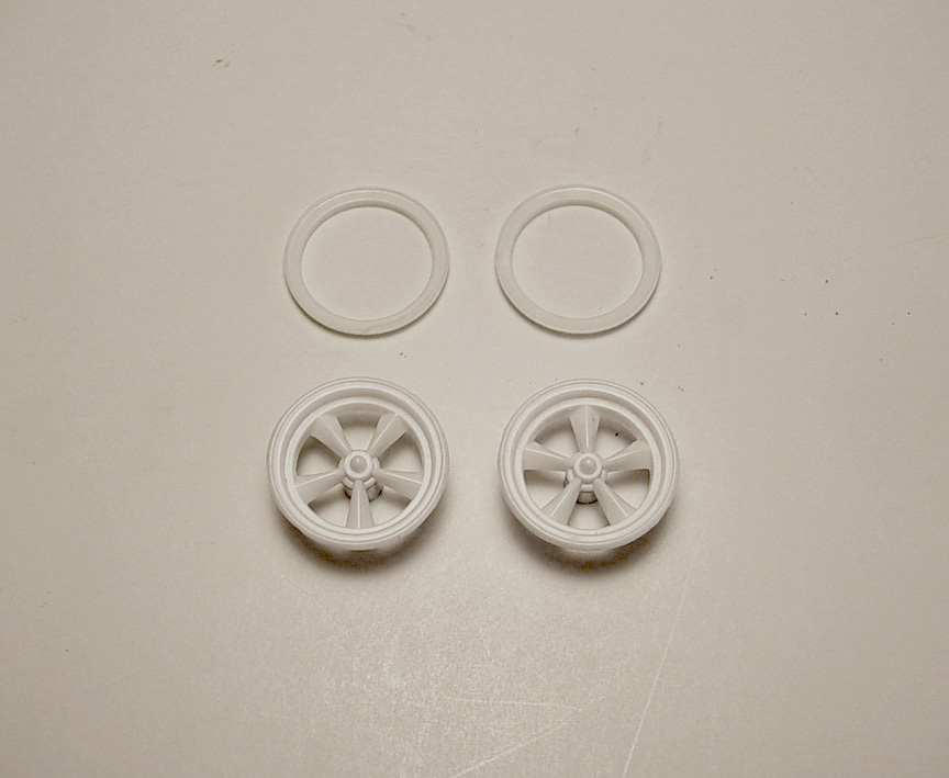 The AMT Cougar Country inner rims didn't match the mag wheels, so I found some that matched closely
and cut them down until they fit the 4" skinny front tires.
The masters are finished !

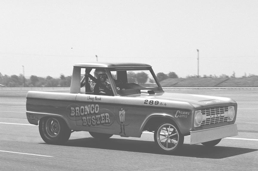
Unlike the previous attempt of a Bronco Buster (eBay resin body) and now Comp. Resin.
Our model is going to be extremely accurate and will come with all chassis and extra parts needed to build a correct model !
Started - 11/26/2016
 2 - Revell Bronco kits will be needed to turn it into a Long Nose Funny Car.
A second body will be needed to do the stretched fenders & hood alterations.
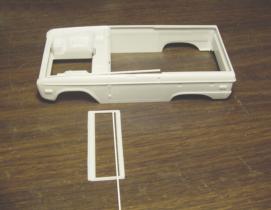
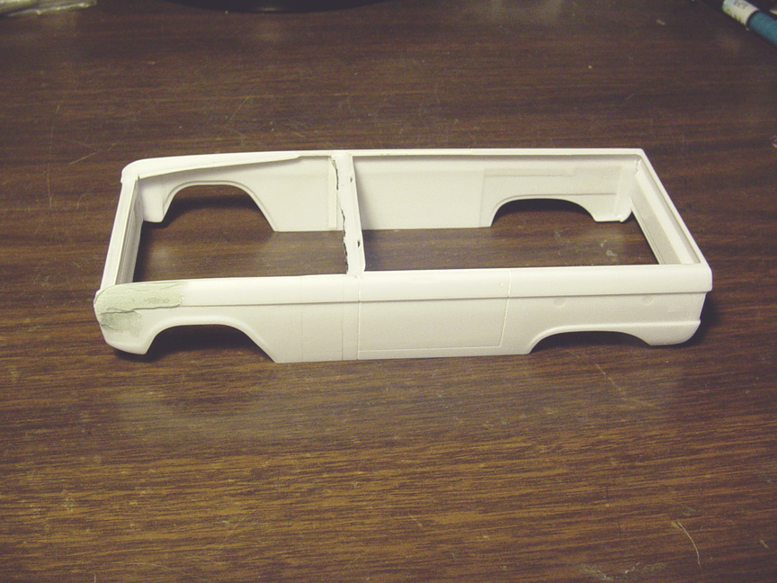
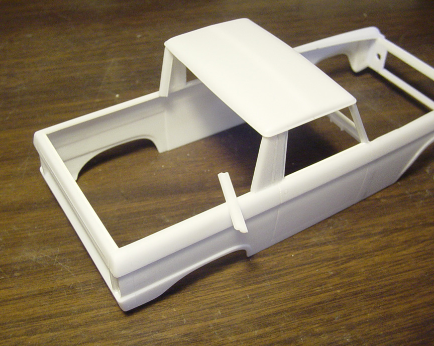
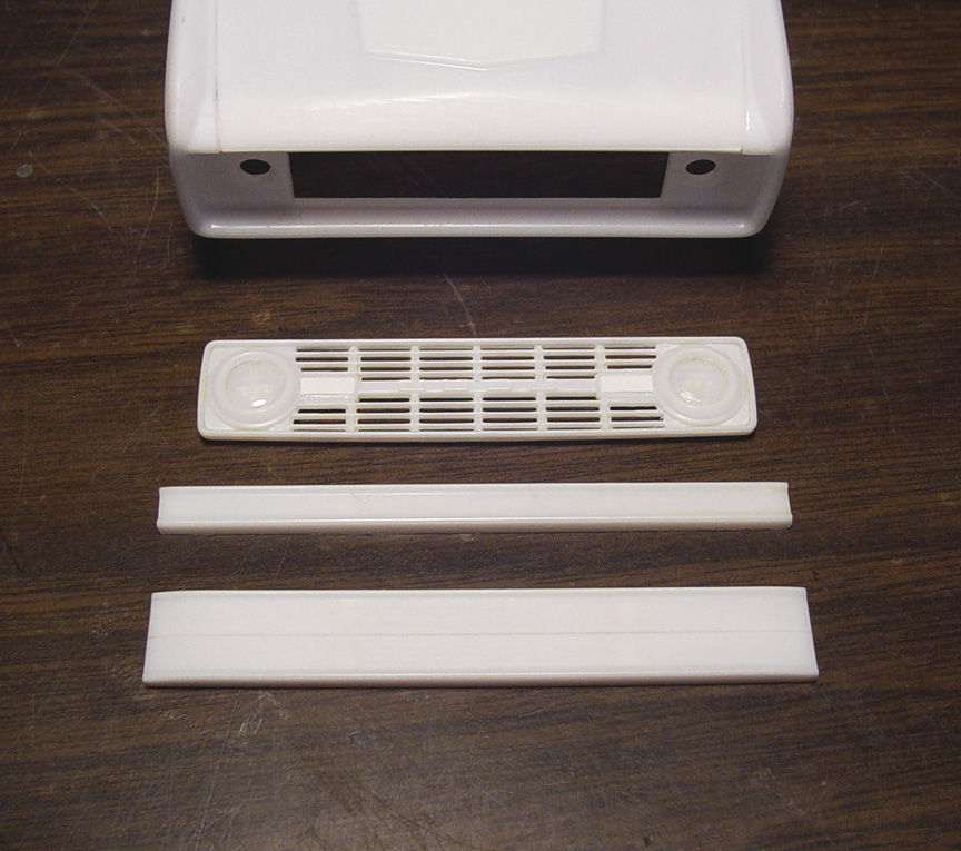
First, to get ready for a 1/2 cab roof, the tops of the door panels need to be filled in with .040 x .060 plastic strip.
The windshield frame doesn't have any chrome moldings as the moldings are in the glass and since this Funny Car doesn't
have window glass, the moldings need to be added using .030 x .040" plastic strip.
 New window moldings !
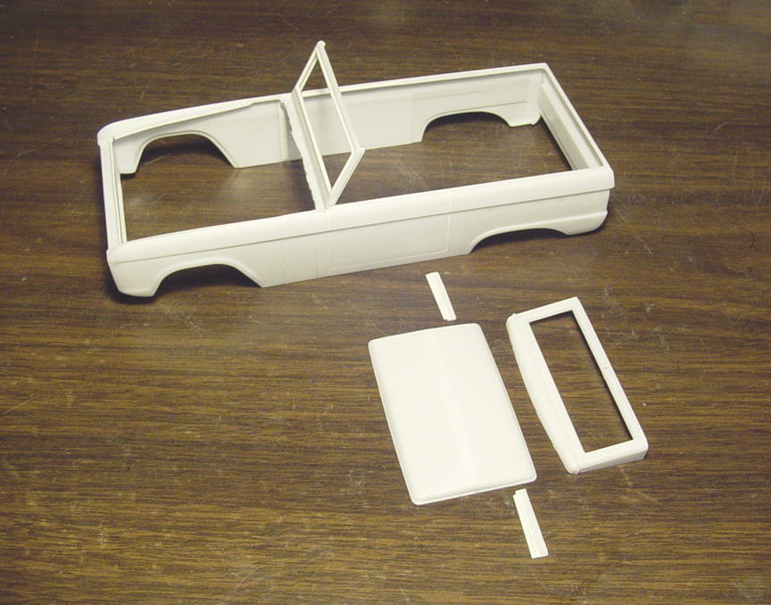
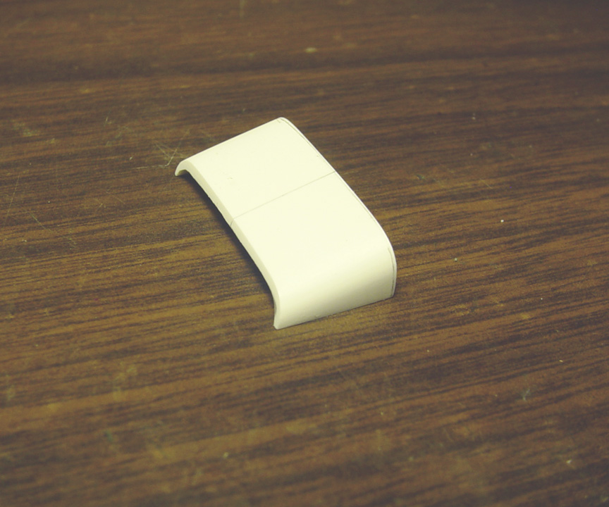
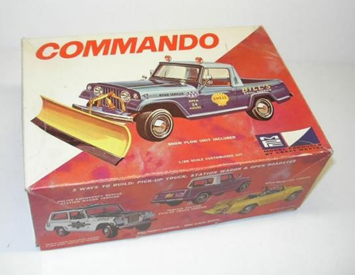 The AMT Commando Jeep comes with a half cab, but I don't have one one at the time of building this, so I'll be scratch building one.
The roof doesn't look right in this MPC kit any way.
 First the sun visors were removed from the head liner on both roofs.
The Sail Panels needed to be 1 scale inch longer, so .030 x .040" strip was used.
 The front of both roofs had to be evenly cut.
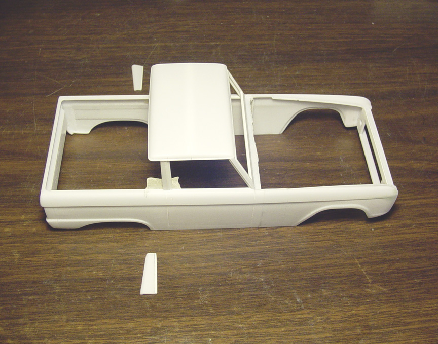
I got the correct 1:1 measurements (from drip rail to drip rail), to get the correct distance of the 1/2 cab roof.
Now that I have the roof situation basically resolved, I want to alter the body before adding the 1/2 cab roof,
as it will be a lot of strain to the roof and it might break off during construction. So, I'm taking a break on the roof for now.
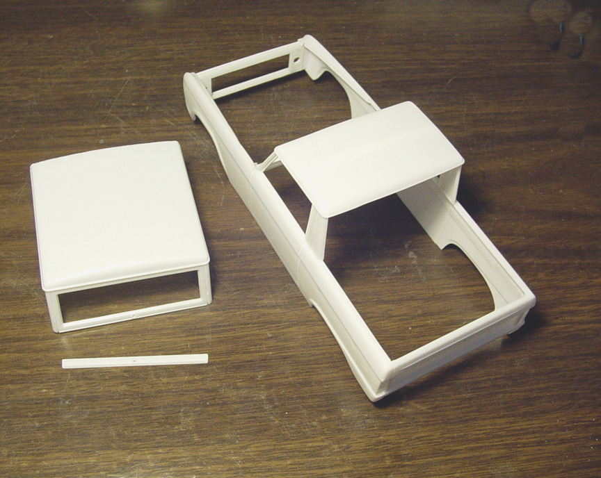
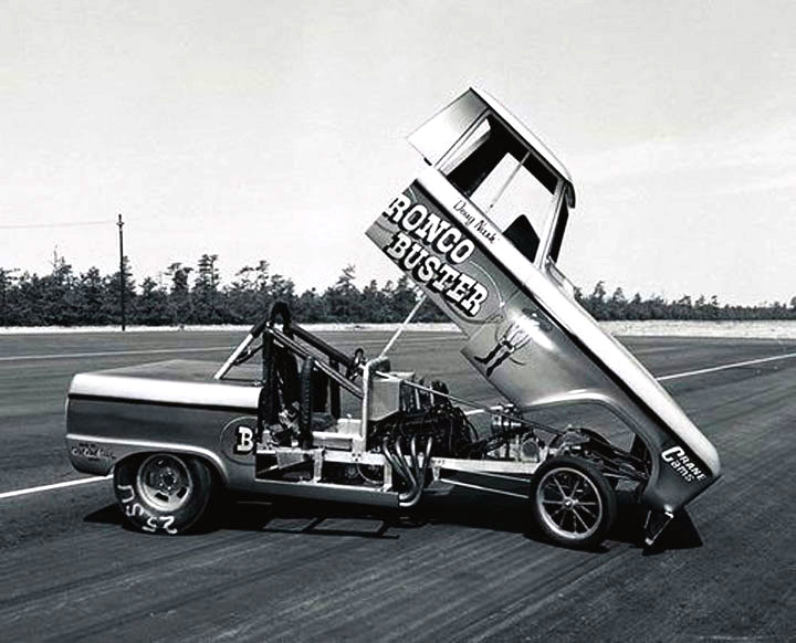
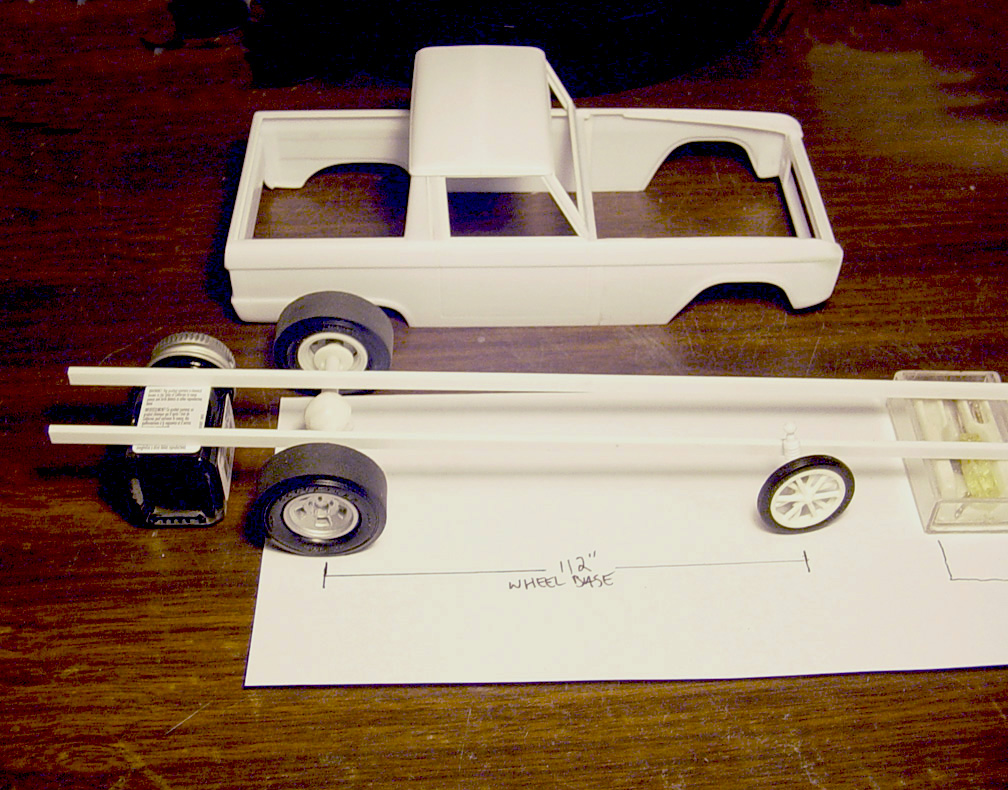
 A stock Bronco has a 92" wheelbase.
The Bronco Buster had a 112" wheelbase, but the wheels are not centered in the wheel wells, so I mocked up where the wheels will sit in the body.
(the rear wheels sit 2" further back from center and the front wheels sit 3" forward from center).
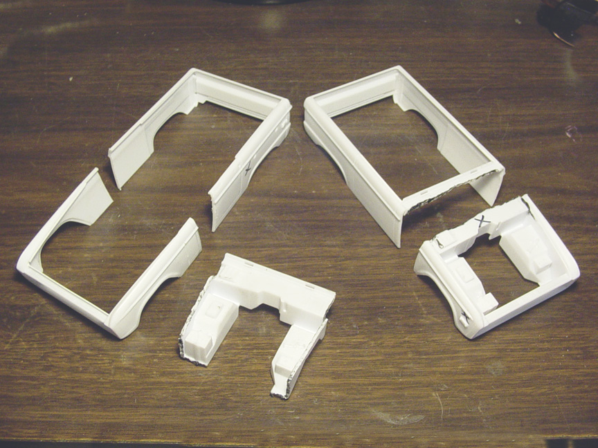
After careful measuring, the body needs to be stretched 15 scale inches !
The rear part of the body on the right will be used as the "master body" and the front clip of the body on the left will be used for the "master front clip".
The bodies with an X on them will be scrapped.
Before making the cuts, The rear master body and front master body panels were cleaned up of all unnecessary emblems.
Holes and imperfections were filled. Marker lights and engine surround were then removed from the front clip.
I'm leaving the belt line chrome trim on, to make sure the body keeps straight when grafting the two body parts together.
 The new "Long Nose" fenders have been added to the body.
There was only one cut line made, the other line is from the door panel filled with super glue.
The cut line was backed up by a strip of plastic inside the body.
The belt line along the body was missing after removing the chrome side trim, so putty was used to create a new belt line.
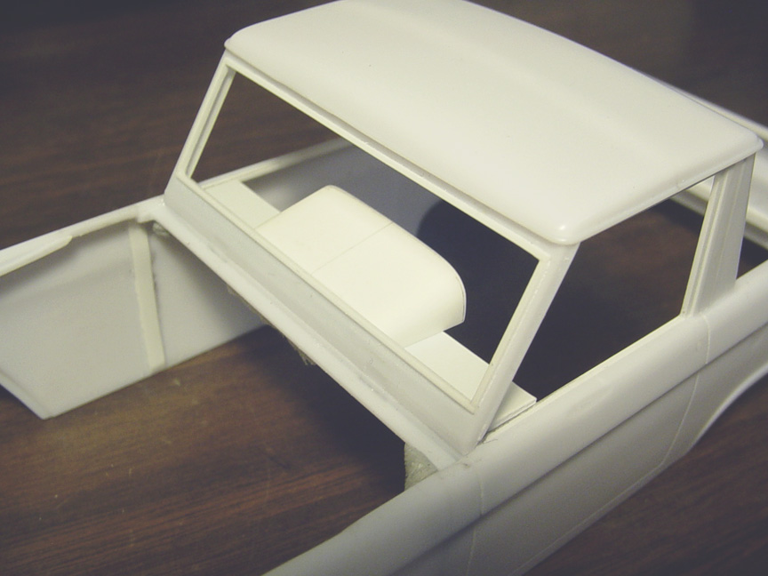
 Going back to the roof......
The windshield was added using the original "wagon roof" as a guide to set the correct angle.
The sail panels will be made using part of the B-pillar from the wagon roof and the rear roof section will be used as the rear
of the sail panel. The angle on the 1/2 cab sail panel has a different angle than the wagon roof, so the angle will need to be corrected.
 The front half of the sail panel was set and the rear half was cut and shaped.
A lot of measuring went into this part of the project !
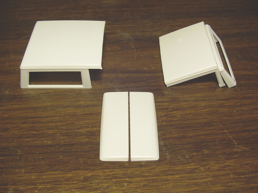
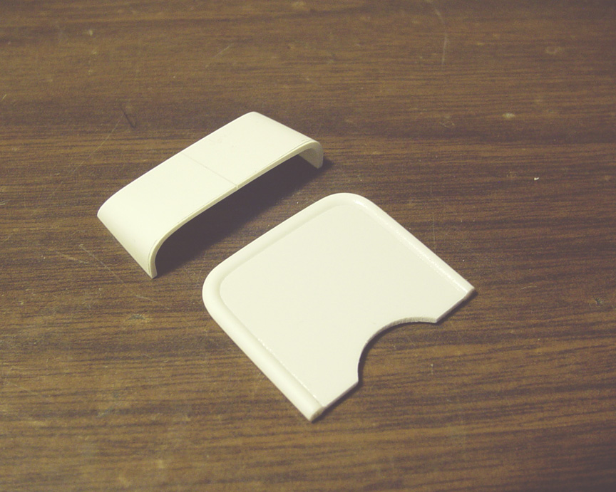
 The sail panel on the 1:1 car has a wrap around to it.
The bottom of the window hatch will be the perfect piece to use as it has a rounded edge and even has a slight lip
to the inside edge, which is on the 1:1 Half Roof.
 Left side wrap around installed, right side is being ready.
CHASSIS

Here's where it gets complicated.
Before finishing the body, I want to start the chassis (since the bed cover & hood is not on the body yet).
I can make building the chassis easier this way and make alterations as the chassis will be more accessible.
 Before starting the chassis, I need to do a mock up to set the wheel base frame height & frame width.
To start all of this, I'll need to build a rear end set up using our Speed City - Ford 9" rear end, disk brakes
(from our Funny Car
Parts Pack), Halibrand 15" Mag Wheels, Inner Rims (Deep Dish) and AMT Goodyear Blue Streak 9:00 x 15" Slicks (found in
older AMT kits). To set the front suspension, I'm using an 18" 12 spoke mag wheel, a dragster tire and coil over shocks from
the Revell Ford Thunderbolt kit to get the correct height of the frame.
After studying photos I set the frame rails where they need to be.
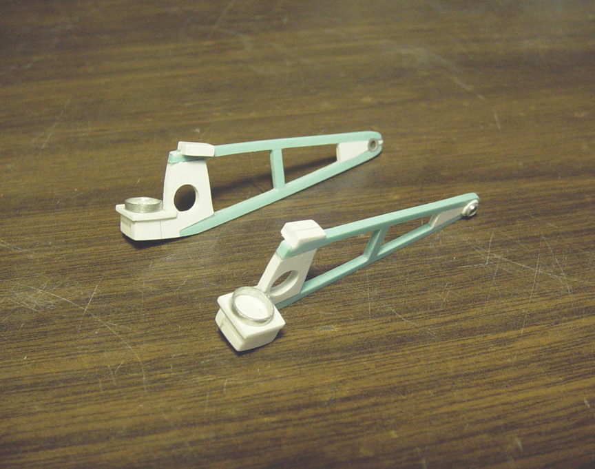
LADDER BARS
 I decided not to take photos of every step of making these as it would have been too many photos to take.
Originally I started with the Revell "Miss Deal" rear Ladder Bars, but it was altered so much that only 3 parts of the rails remained.
10 separate pieces of plastic were used to make each ladder bar. After spending 4 days on trying to come up with
an easy solution for a rear suspension, here's what I came up with.
 I made cheater blocks on top of the Ladder Bars so the frame can rest on them for easy assemble.
The coil springs are from the Revell Ford Thunderbolt.
 UPDATE: Some new changes were made to the Ladder Bars as I didn't like the way they were fitting, and they were too close to the slicks.
I moved the coil springs 2" closer to the frame, 2" higher and 1" closer to the rear end by adding a new shock mount and shock ring (from aluminum tube).
I need to keep the bottoms of the shock mounts thick due to casting reasons (but, that can be sanded down).
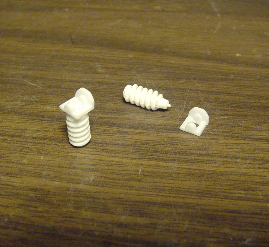
The pressure fittings on the tips of the Ladder Bars were made from punching out .010" sheet plastic, to be used as a washer,
then drilling through the center of the washer and adding an aluminum tube through the hole.
The cheater blocks were also shortened. 13 separate pieces of plastic & metal were used to make each ladder bar.
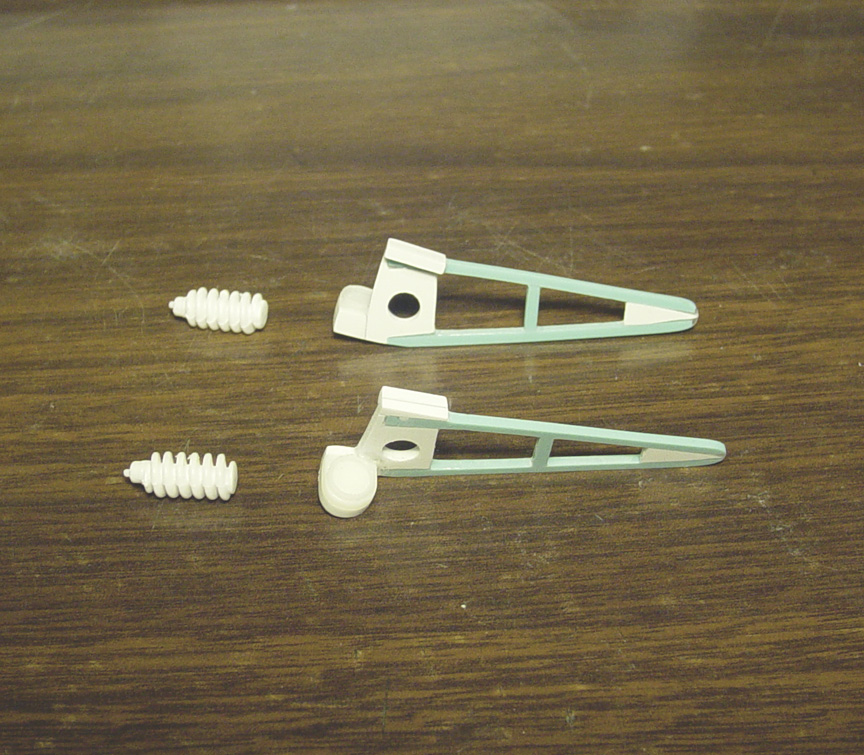
 New updated Ladder Bar Suspension !
It's taken 7 days labor (about 46 hours) to make these parts work on the frame rails to set the rear suspension, but it will save
a lot of time and frustration for all you builders that have been waiting to build a "correct" Bronco Buster Funny Car !
The entire build rest's on these Ladder Bars and will be the key component to building your model.
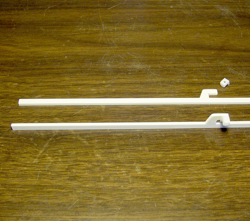 .050 x .156" plastic strip will be used as the Frame Rails.
The front Shock Towers were made from 2 strips of .080 X .156" stacked, glued and shaped.
The Shock Mounts were cut from the Revell Bronco frame and glued to the Shock towers.
 Before starting the chassis, I first had to make sure that the front Shock Mounts will fit the Revell "Ford
Thunderbolt" coil over shocks that are being used on this Straight Tube Axle.
Using an old resin 18" 12 spoke mag wheel and some Goodyear Dragster Tires. "QUAKE HOLD" museum putty was used to
temporarily hold the shock to where the center of the tube axle will be. Since I don't have accurate dimensions on the chassis
width. I went by photos, and what made sense for the tread width.
After finding the correct 112" wheelbase, the holes in Ladder Bars were drilled through the frame rails and a .062" round tube will be used as locator pins.
 Rear Shock Mounts were cut from the Revell Bronco chassis to be used for the Coil Spring Mounts.
 Rear Shock Mounts installed - Here you can see how the rear springs will fit.
 I set the Radius Rod Bracket by using a set of Polar Lights Funny Car Radius Rods.
Pre-drilled the holes and then backed it up with the same frame square tube to make it as wide as the frame.
I have to simplify these brackets and make them thicker due to casting reasons.
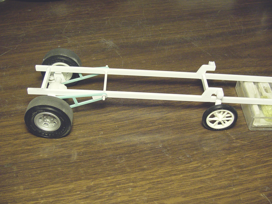
 Here's how the front & rear suspension will look with the Straight Tube Axle & Coil Over Shocks
and the Revell Polar Lights Funny Car Radius Rods, set to the correct 112" wheelbase.
 The rear frame rails are now installed.
The rear part of the frame rail will be used to set the body to the chassis.
 .080" square strip was glued to the inside of the tailgate for a body-to-chassis mount.
This is a signature move I use on a lot of my masters to make it easy for you the set the body to the chassis.
 Using an AMT '67 Mustang 289 Ford small block engine to set the motor mounts,
I cut the motor mounts off an AMT Hogan's Hero's Jeep. Plastic sheet was used to build up the bottom of the motor mounts
to make them thicker. The Transmission mount was made from drawing out a stencil of what the tranny mount looked like
and re-shaping it to fit the angle of the engine to meet the rear end.
Also: The Radius Rods bracket was removed, since I thought it was a waste of using a Polar Lights F/C/ kit just for the
radius rods. The Revell '27 'T' Roadster will be the donor for the radius rods and it already has brackets on the rods.
COWL
 There's not much for the body to rest on since there is no interior tub.
The goal here is to make the cowl rest on the firewall to hold up the front of the body
This will be essential, especially if your planning to make the body flip up, then the cowl will need to fall back down and rest
on the firewall to hold up the front of the body.
 Starting with a front section of an AMT Double Dragster body (because it had a nice curve to it),
the part was altered and sectioned to fit the outside of the frame rails.
 To make the cowl level, a temporary piece of 040" sheet was used.
.020" sheet
will be needed for the top of the interior tin on your build.
To make the interior tin.... fit a piece of .020" sheet inside the body, glue the cowl to the sheet and remove the
center section (where the driver sits).
FIREWALL


Since this model has no interior tub, the firewall is going to be the part that will hold the body up.
 After many hours of test fitting, so that the cowl will rest on the firewall and the transmission will fit through the
firewall, .040" sheet was measured and cut to fit the inner frame rails. Then .080" rod was glued around the sides of the firewall.
 Here the firewall is temporarily set to the frame.
 The cowl & firewall are set and the body will now be able to rest on the firewall.
This is especially important if you will be making the flip front end.
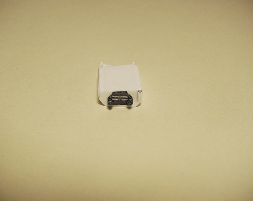
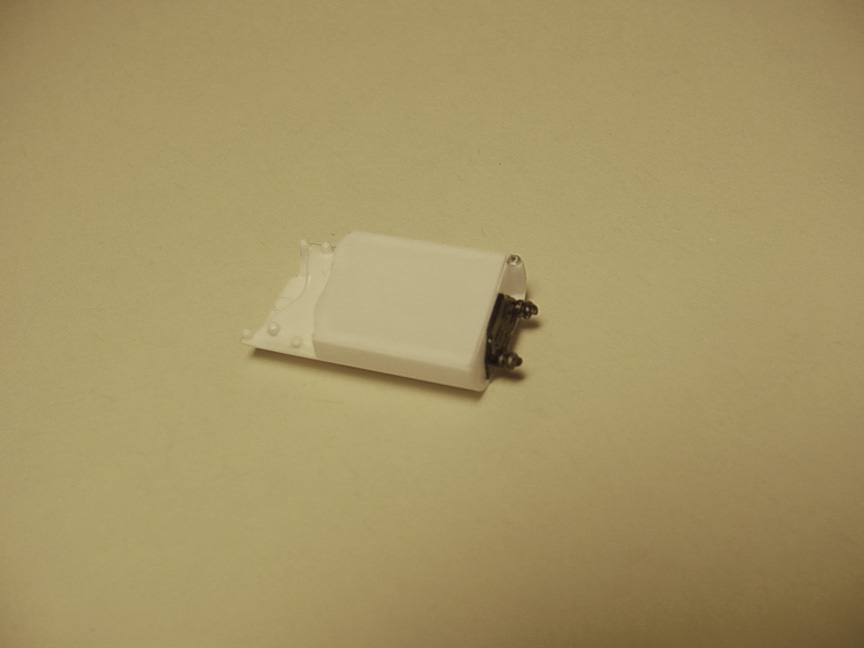
 To make the Gas & Brake pedal boxes, I'm starting off with 2 battery's from the Johan Chrysler Turbine Car,
since they were the thinnest wall battery's I could find.
The 289 engine had to be mocked up in the chassis to make sure the gas & brake pedal boxes will clear the valve covers.
 In my haste to get this finished by the end of the night.....
I thought that both boxes had the same chopped angle on the bottom (but, I was wrong) and paid the price to make it right as
I had to fix the flaw with 4 pieces of .040" sheet plastic.
 To make the instrument panel, I'm starting by using a "gauge cluster box" from our Speed City '66 Long Nose Barracuda Funny Car and cutting off 2 of the gauges to be mounted to a .040" sheet as a base.
 I masked off the firewall to spray primer inside the boxes to check for imperfections, but didn't want primer on
the middle part of the firewall. The Gauges were glued on and 3- power switches were made from .010 x .030".
The switch bases and the switch covers were made with .010" x .020".
A starter button was added using a water cap cut from one of the Johan battery's.
BACK TO THE BODY
 The main hood was bent back and sanded flat to make even at the rear for the other half of the hood,
so they will match when fitted together.The vents on the Revell Bronco hood are hollow, but for the Funny Car version,
they need to be back filled with plastic pieces. To make the bed cover, .040" sheet was used.
 Another hood was needed for the stretch and the vent holes needed to be completely filled on that hood.
Plastic strips were added on each side to fill the gaps between the hood & fenders.
 All the seams on both hoods have been filled with super glue & sanded to perfection.
To start making the hood scoop, I first need to figure out if the injector stacks will fit through the hood scoop?
LOOKING FORWARD... I also need to make a "Ford (small block) Injection Manifold & Timing Cover".
Since no model company ever offered one, I'll need to scratch build that too !
I started the base of the Ford (small block) Injection Manifold using plastic strips & sheet to fit on a Amt/Ertl 1967 Mustang GT
289 Ford small block engine. I now have a basic idea of how wide to make the hood scoop.
(I'll get back to making the "Ford 289 small block Inj. manifold" later)
I thought of using brass or aluminum sheet for the hood scoop, but it would be difficult to make a hole in the hood and then
try to fit a metal scoop into the hole. It just sounds messy.
I'm making the scoop from a bottom of a Sprint Car belly pan, cut in half, thinned and shaped to look like the B.B. scoop.
 The Hood Scoop was mounted to the hood with a light bead of ultra thin super glue and the hole was cut out
from beneath hood.
 After consideration of having separate taillights or mounting them to the body ?
I decided to keep the taillights on the body !
The Tail Lights can be lightly masked off with Bare-Metal Foil
when Priming & painting and then re-foiled after painting.
 The body is now ready for a final sanding & perfecting before a primer coat.
BUMPERS & GRIL
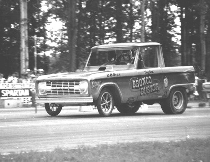
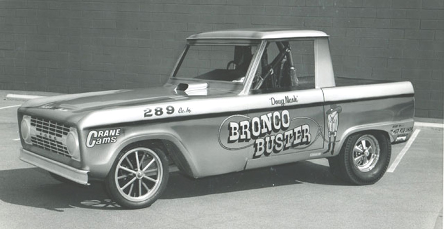
The Bronco Buster ran with 2 different style bumpers.
The early 1966 version (with the Halibrand rears mags) mainly used a "Big Bumper"
Although the early version did change to a standard bumper later in the year (center photo).
The standard bumper was always on the 1967 version (with the Cragar rear mags).
 The early version "Big Bumper" was made using 2 bumpers glued together and the center sanded smooth.
Both bumpers were shortened on both ends.
The clear marker lights for the grill didn't sit right and didn't look like the fiber glass versions, so .010x .080" strip was glued
over the tops of the marker light holes. The clear head light lens's were glued in to resemble the fiber glass grill on the B.B.
Finished - 4/20/2017
The master is finished !

I personally guarantee this to be the only correct Bronco Buster ever made !
I still have the issue about making a Ford (small block) Inj. manifold-
Timing Cover & new 6" Stacks that are needed for the Bronco Buster.
Also: A new correct set of 18" 12 Spoke Mag Wheels will be coming soon.

#SC- 105
Injection Manifold - Timing Cover - New 2x6" stacks
ALSO: New 2" diameter x 6" tall stacks (in scale) will need to be designed to fit this new Injection manifold.
No model company ever made a 1/25 Ford small block injection manifold or timing cover.
Since our new Bronco Buster Funny Car need's them, they will have to be created.
Ford Small Block Injection Manifold
 To start, an AMT '67 Mustang 289 Ford small block engine was assembled.
.030" sheet was used to make the 3 sections of the base of the manifold.
Lines were drawn to where the tubes will be set.
 .080" hollow round tubes were individually cut to fit the angle of the base.
I thought of drilling the tubes through the base, but the base is too fragile.
By adding them to the top of the manifold, I can better control how the tubes will line up.
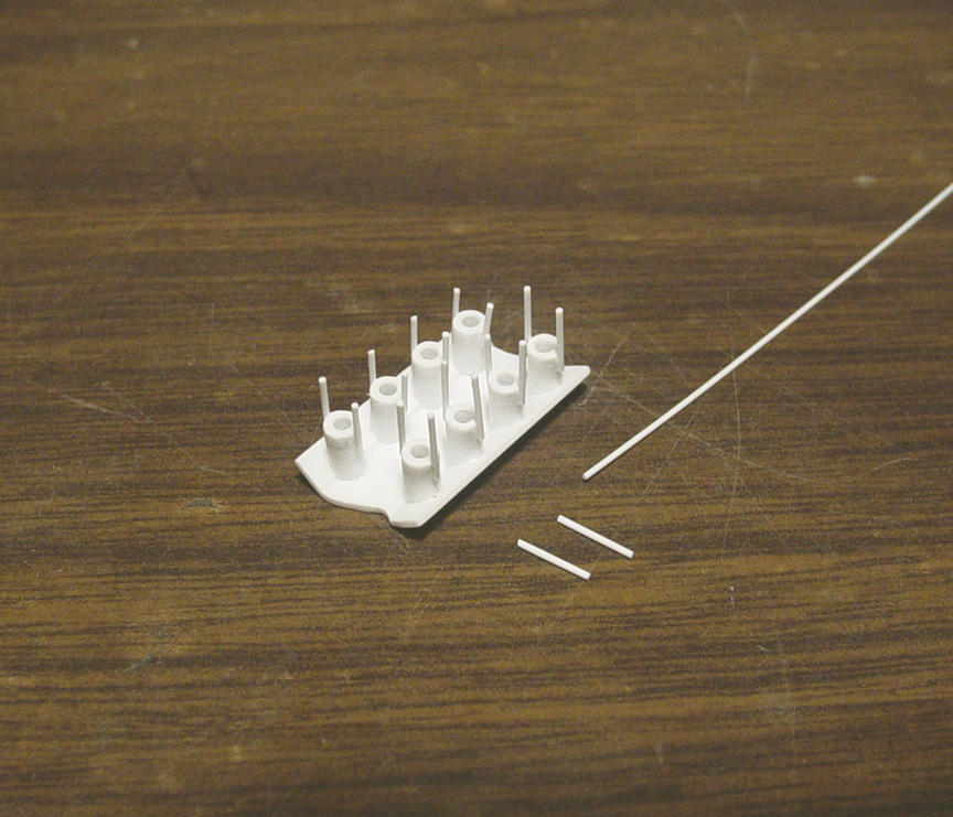 16 pieces of individually cut .015" round tube was used to make the set screw base's.
 .047" rod is used to make the mounting pins for the injector stacks.
 The water line plugs were made from .062" rod.
The fuel block made from .060 x .100" strip and the cooling fins from .015" rod.
 10- Pro-Tech .020" bolt heads were added to the sides.
Ford Small Block Timing Cover
 It took 31 separate parts to create this "Ford Small Block Timing Cover",
using plastic strips, round tube and 8- Pro Tech .020" bolt heads.
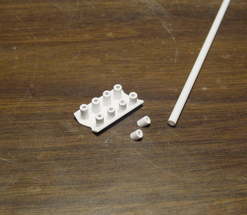
Ford Small Block 6" Injection Stacks
 We had to special order new stacks for this Small Block Injection Manifold.
These new stacks have a 2" diameter x 6" tall (in 1/25 scale).
These new stacks have a bigger diameter than our other 6" stacks we sell for the Buick Nail Head Engine.
Master is finished !

#SC- 106
Our goal is to create the only accurate 18" 12 spokes ever made !
 Starting with The Mag Wheels from an Ed Roth "Mysterion", as the rims are 18" in diameter-
and they have correct 2 step rims. The chrome was stripped and the dish was removed on both wheels.
The rims were then sanded and polished smooth.
 (Top) The spokes on the Monogram "Boot Hill Express" are too long, but I can cut them down to fit the
Mysterion rings, so they'll make a perfect contender for this project.
(Middle) First, the chrome was striped off the "Boot Hill Express" inner & outer wheel.
The back side of the Boot Hill spokes are flat, so every spoke was thinned down and rounded with a jewelers file.
The space between each spoke had to come in closer to the center hub on the outer rim.
The large holes on the back side of the Inner & outer hubs were filled and new holes were drilled to fit a standard axle.
(Bottom) Each spoke was cut from the Boot Hill wheels and carefully sanded down to pressure fit the Mysterion ring.
The dust cap was removed and the washer was sanded down just before the spokes.
 The spokes were re- thinned again and oval shaped. The center hub was sanded down even closer.
A washer was made with .010" sheet using a punch. To make the dust cap,
.062" rod was used, but was rounded and
polished before installation.
 The spokes were mated to the rims.
Then a small bead of super glue was added to the bottom of all the spokes and polished out.
Finally, the Boot Hill valve stem was removed and added to the new rim (on the correct left side of the spoke).
These 2 wheels shown are a "front & back" for only one tire.
A casting will need to be made from these 2 wheels and then a new mold will be made for several sets later.
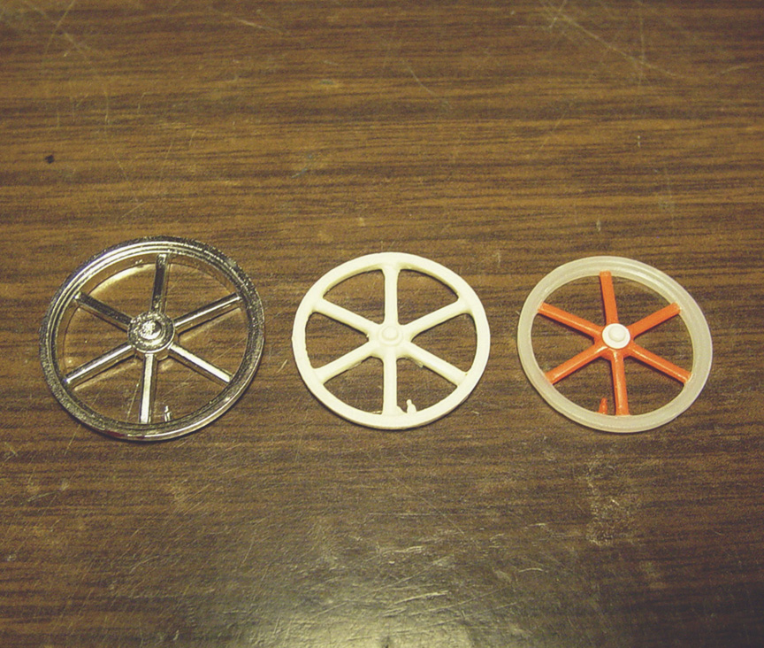 You can see that the Boot Hill Express wheel & the competitors resin wheel, has the valve stem on the wrong
side. Also, the competitor's resin wheel doesn't have an angle to the spokes (they lay flat) and only has a solid ring for a rim.
 Here's the master on Goodyear Dragster Tires.
 After making a mold of the master 2-piece Inner & Outer wheels,
A bunch of mag wheels were cast and then cleaned up of all flash to make a single multi-piece mold.
10 mag wheels had to be cleaned up to be used as masters.
Master is finished !
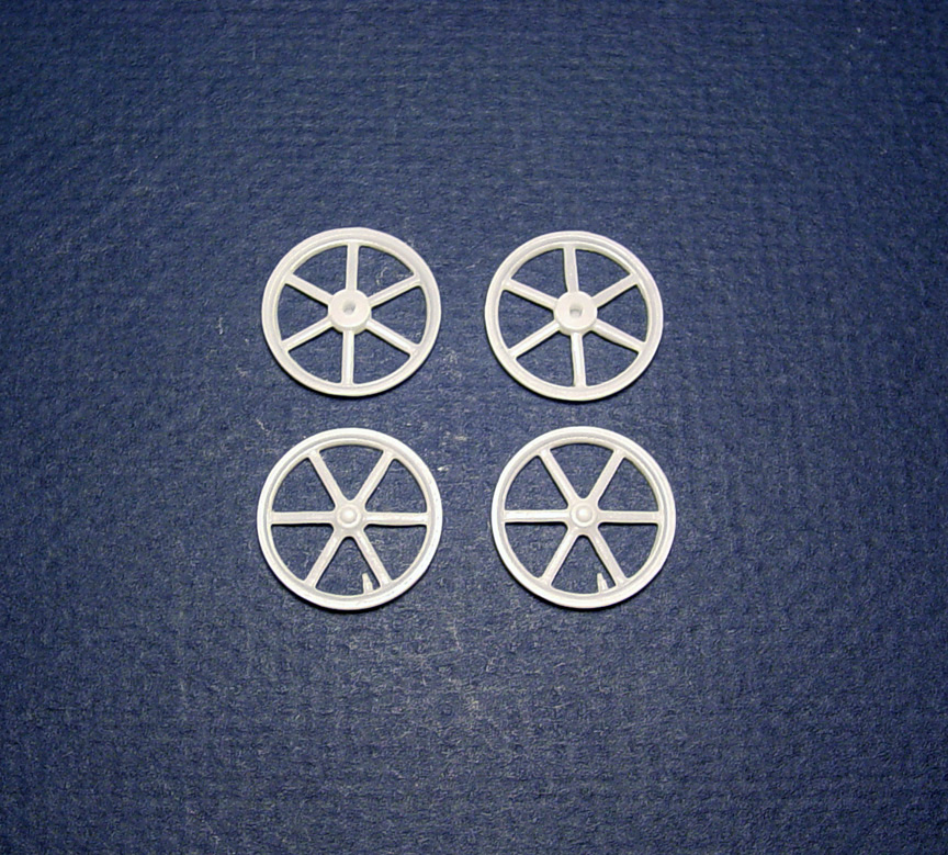
We'll finally have correct 18" 12 spoke mag wheels in 1/25 scale.
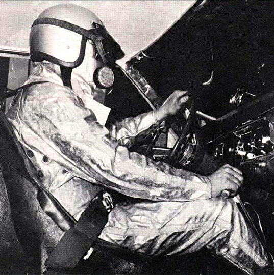

I've been wanting to do a driver figure for many years now !
Although there has been many driver figures made, I haven't found one that looks accurate to scale,
and it would be too hard to make any one of those figures fit into any style seat.
The plan here is to create the most accurate looking driver figure ever made and make it possible to fit all seat's.
With two sets of arms - * bent and extended *
Though there were many types of fire suits made, Deist, Bell, Ansen, etc.
This figure will be based on a '60's-'70's Simpson Fire Suit and Mask.
 Going through the box of driver figures saved over the years, the best pieces were picked out of the lot.
The head is from the MPC Blue Max Mustang Funny Car, as it had the best "full face mask" 1/25 scale head.
The torso and legs from a Monogram 1/24 sprint car figure and some nice looking parts box extended arms.
The left hip needed to be wider to sit in the seat straight, so .080" plastic was added to that side of the leg.
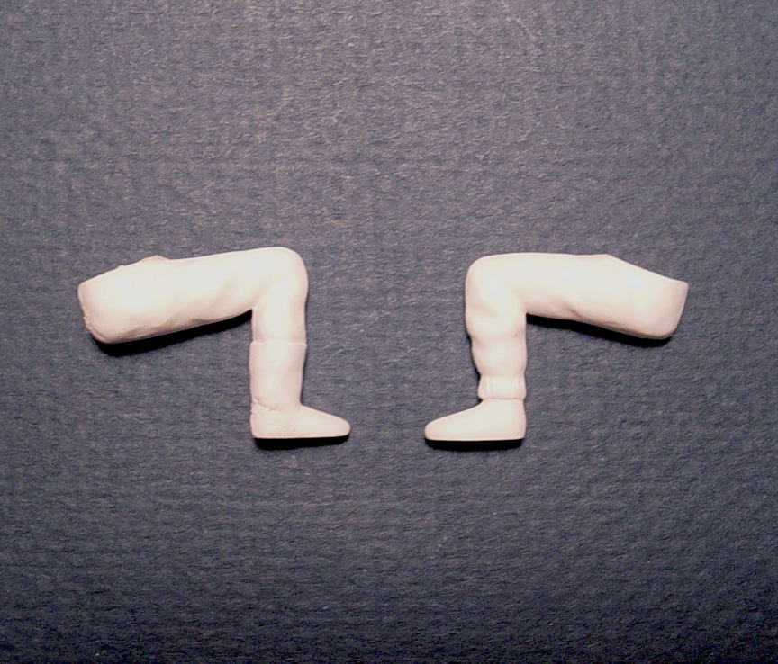 The pants from the 1/24 sprint car driver has elastic at the bottom and since this Funny Car figure
needs boots, .010" sheet was used to wrap around his leg to resemble a boot (shown on the left).
Liquid cement was heavily applied, so the plastic would melt to fit the leg indentations.
These legs will go through a long process of making them look more correct later.
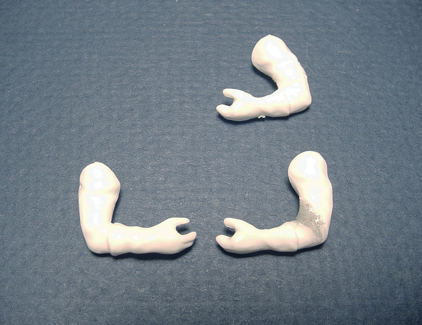 The right arm has the correct angle, but the left arm doesn't meet the steering wheel properly.
So the left arm was cut in the elbow to bring it to the same angle as the right arm.
It was also brought into the body more so the figure will fit into a tight interior tub, (the original arm is shown above).
The left glove will need to be removed and relocated to match the right side glove.
I'm just roughing these arms in right now, later they will be re-shaped with all new folds & wrinkles in the fabric.
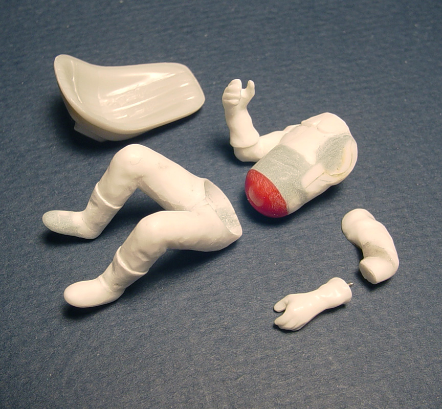 A basic AMT Chevy II Funny Car seat is used to set the legs and torso to,
as it is probably the lowest seat available.
I'm also test fitting the legs & torso to other drag car seats as I'm going along with this Driver Figure.
1. Starting with the legs.... The legs were re-shaped to 1/25 scale and the hip socket was rounded out.
2. A helmet from a red plastic 2nd sprint car figure was used as the ball joint for the bottom of the torso.
3. The original torso had some detail that was removed (especially the neck brace), belly & sides of the body were puttied.
4. The left hand needed to be at a different angle, so it was cut off and a piano wire was used to help set the hand and to
make it stronger during
casting. The ball and socket joints will make this figure fit into any seat !
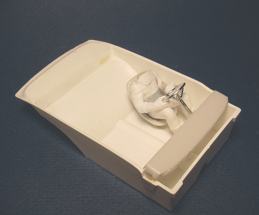 Figure in a Chevy II Funny Car.
In all fairness, The steering wheel on the Chevy II is too low and should be raised.
But since this is such a shallow interior tub, it should fit even better on other interior tubs.
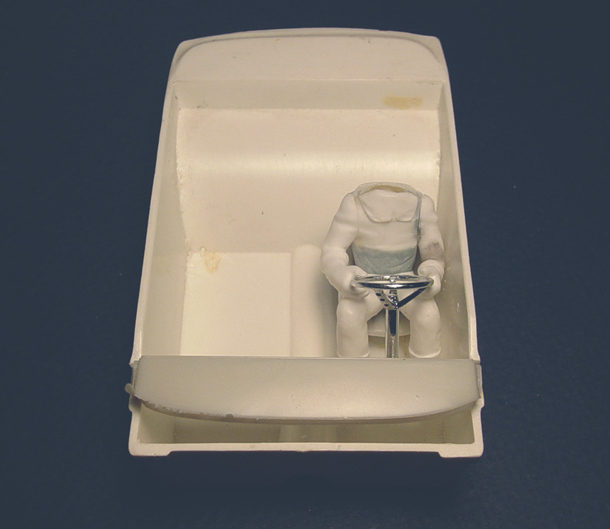 The left arm was pulled into the body more, so it will fit into tight interior door panels.
I thought it would be a great idea to have 2 different sets of arms.
One set of short arms to hold the steering wheel and another set of of extended long arms.
This will give about 10 different ways to make the figure and it would look different in each car you make.
* right extended long arm could hold the stick shift, or the steering wheel or be waving.
* left straight extended arm to hold the steering wheel, hanging on the door (like Wild Willy Borsh) and even
waving.
There's many possibility's there !
Keep in mind this is still a work in progress, the finished figure will look much better.
EXTENDED ARMS
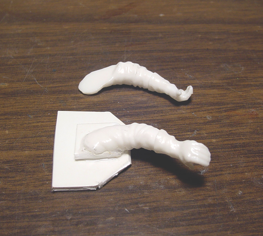 To make the left extended arm be more poseable, the left hand needs to be knuckles up.
This way, the left arm could be holding the top of the steering wheel, hanging on the door or waving outside.
To fix this, 3- pieces of .080" plastic sheet was used to build up the under arm.
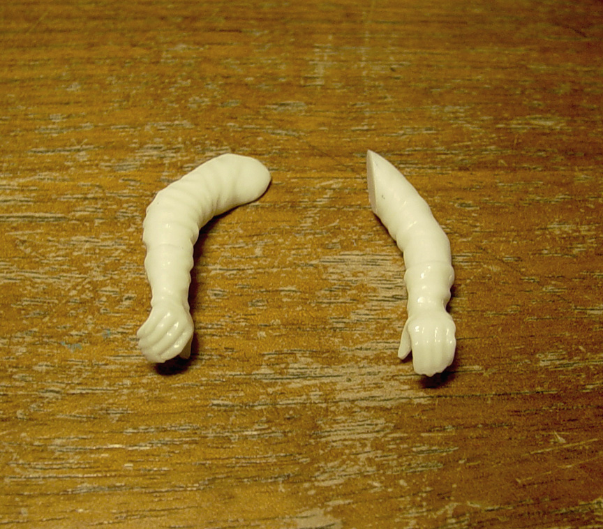 Here is the new left extended arm re-positioned with the hand "knuckles up" next to the right arm with the hand
in the side position. The same thing will need to be done to the right arm !
Extra length will be left on the back of the extended arms, as it will be needed for your personal arm position.
DRIVER HEAD
I want the head to be a separate piece, so the head can be angled back or forth.
This is crucial because if the head is part of the torso, it can't be corrected,
and your head will be staring into the sky or headliner.
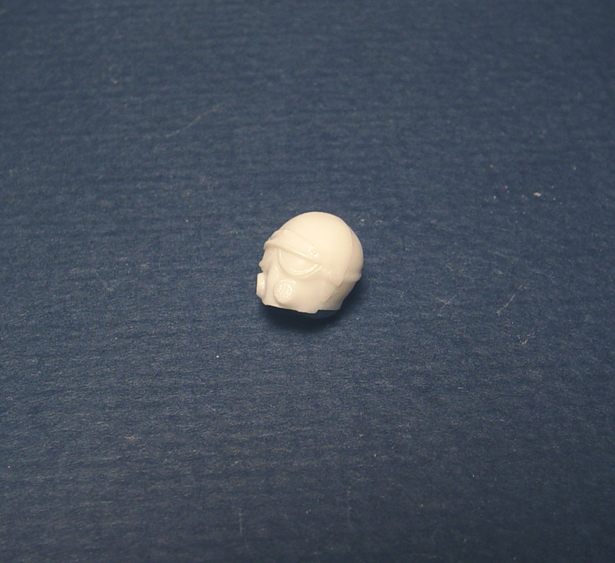 This MPC Blue Max head is a good starting point but,
the top of the goggles are hidden under the visor and I want to see the full goggles.
Besides that, if you were to paint the visor black and the goggles black,
there would be no separation between goggle and visor.
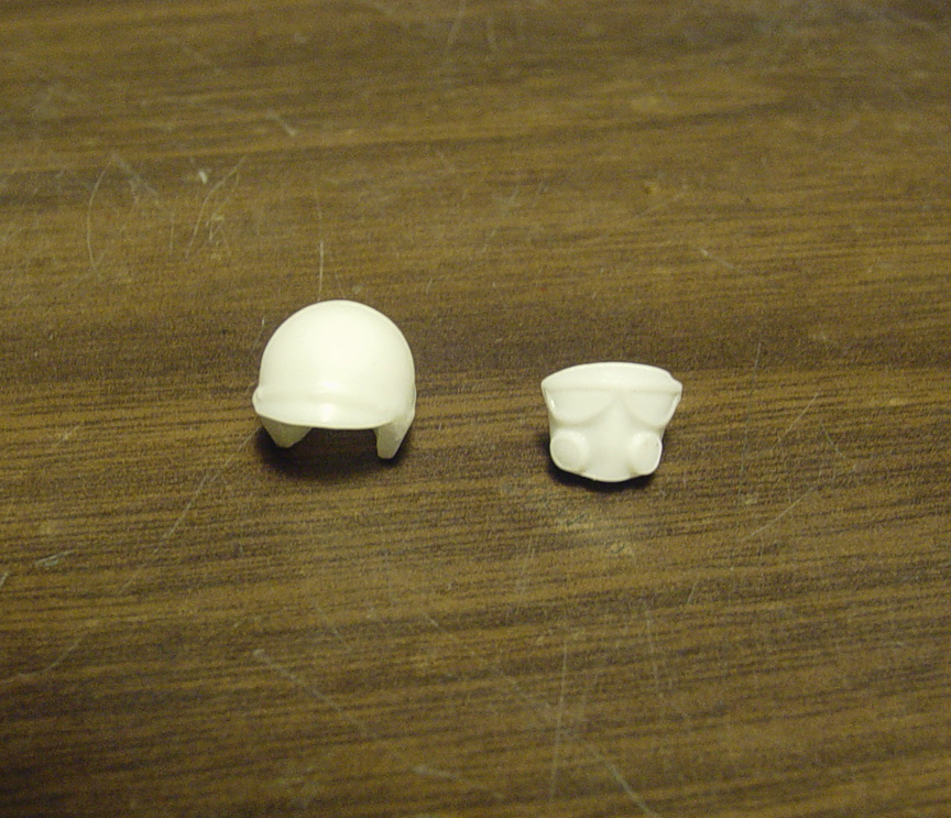 It will take (2) MPC Blue Max F/C driver heads to make a full goggle and have a separation between the
goggles and forehead. I'll need to cut out the face on one head to save the helmet, and cut up the helmet on the other head
to save the face. I'm keeping the visor on the helmet with the face and shaving the visor down to make the top of the goggles.
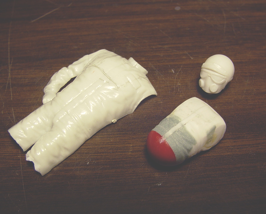 Here you can see the goggles are lower, the breathers, helmet sides and goggle straps have all been
cleaned up and are more pronounced. Also: a zipper guard has been added to the torso from .010 x .040" strip.
I'm thinking of using the chest of the Revell Don Prudhomme figure (shown here) for the face cowl ?
Well, The Prudomme figure for the cowl did not work out, so I decided to scratch build one out of .015" sheet.
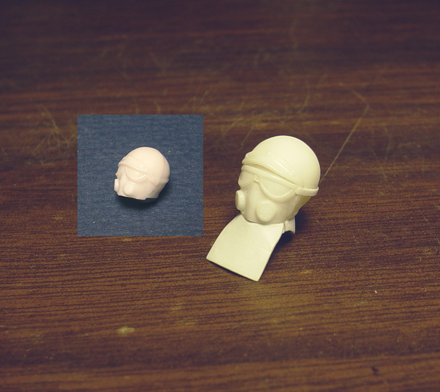 To finish the head --- .010" rod was put between the 2 goggle lenses to give a separation between the lenses
and to help them to look more realistic.
The old goggle strap around the helmet was removed and a new strap (with cleaner lines for painting), was added using
.010 X .030" strip. The edging around the helmet was also cleaned up to be more pronounced.
The 2-piece cowl was made from .010" sheet (front & back sides) and shaped to the shoulders on the torso.
The underside of the cowl was filled in with putty by wrapping the torso tightly with saran wrap and fitting it to the torso.
Once the putty was dry the saran wrap was removed to have a perfectly shaped cowl to body.
I'm leaving a little bit of the chin, as you may want to remove the cowl and make the fire suit look like the cowl is tucked in
and the suit is zipped up.
I'm not extremely happy with the shape of the google lenses, but it would be too hard to make new ones and I don't think
the ends would justify the means.
 Here's the figure in a Speed City A-100 Seat.
This seat is one of the tallest seats and has a high straight back.... and the figure fits !
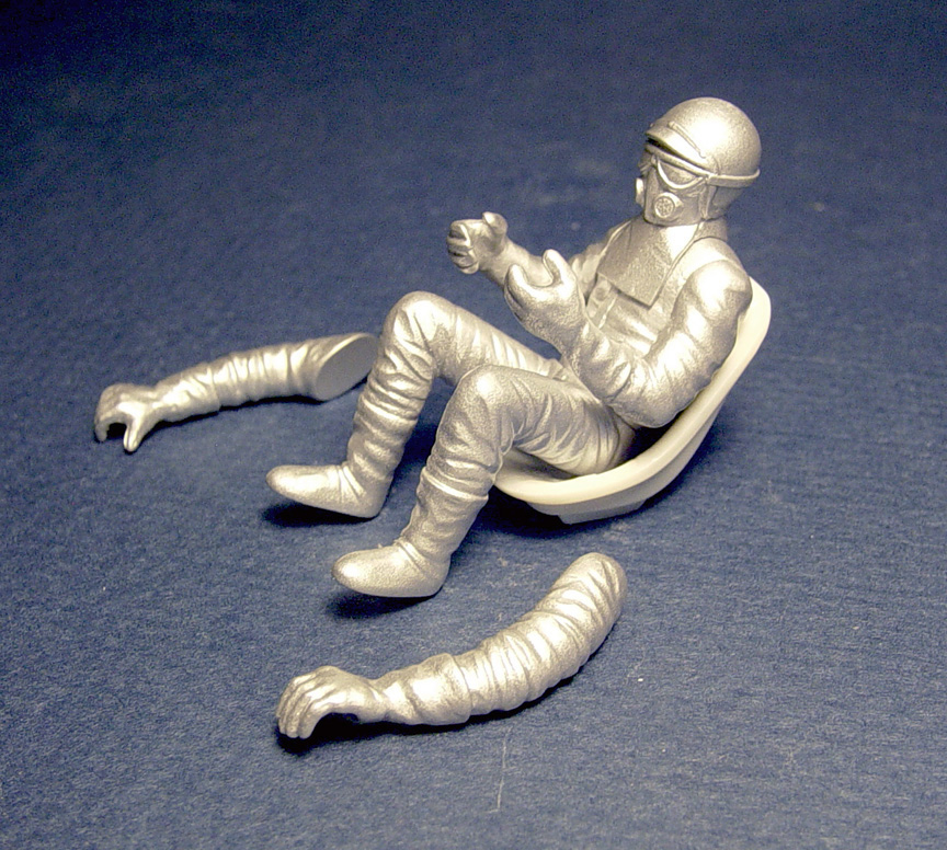 Here's the figure in a Rat Packer Funny Car seat.
This seat is one of the lowest seats and has a tilted back.... and it fits !
Out of all the different style racing seats, these two seats are the most different in shape.
The figure fits them both with no effort. I literately just dropped them in the 2 seats.
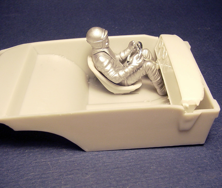 Driver in a Rat Packer Interior Tub.
You will need to alter the seat location to make the figure fit due to the incorrect seat location on the interior tub.
Master is finished !
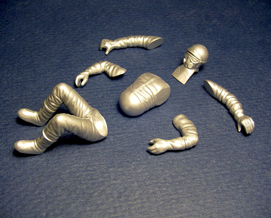
All the folds and crease's in the fire suit were done by hand using different sized jeweler's files,
sand paper & polishing wheels.
UPDATE:
I wasn't satisfied with the old helmet, so a bottom section of the new helmet was added to the old helmet.
Putty was added to the helmet sections, nose and lower mask.
Taller breathers and deeper recessed goggle lenses' will be added next.
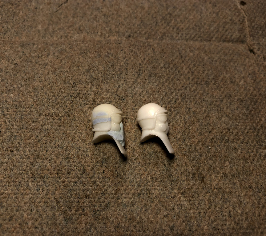
New & Improved head:
Now has corrected helmet, taller breathers, longer nose, longer face, deeper recess in goggles & no goggles strap.
Goggles strap can be made easy with pin stripe tape.

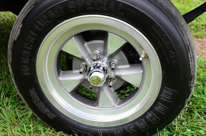
Unlike the original Johan 14" Lemans mag wheels, These new Lemans mag wheels are being corrected into a
15" rim size, larger spokes, axle hub and separate inner rims and will fit most standard size and skinny front racing tires.
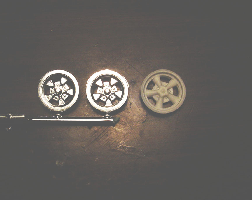 As you can see the (chrome) Johan Lemans mag wheels are smaller than a "Speed City Resin" American Racing
5 spoke 15" mags, as well as the spokes being too small.
Also: More importantly, the Johan mag wheels will not fit on standard tires as they were made to fit Johan promo style
14" tires.
 After doing some research, it was determined that the spokes on the Lemans mag will need to be longer
to make the spokes look more like a natural 15" mag wheel.
The chrome was stripped from the Johan mags and the rim between the spokes were cut out.
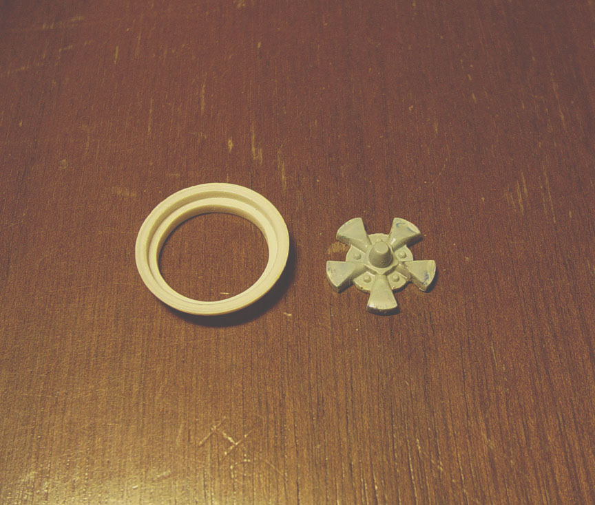 (On the left)....A Speed City American 5 spoke mag wheel had the spokes removed.
(On the right).....
The leading edge of the rim was removed on the Johan mag to be able to fit into the new American trim ring,
and each spoke was sanded flat to match the original flat spot on the Lemans spokes.
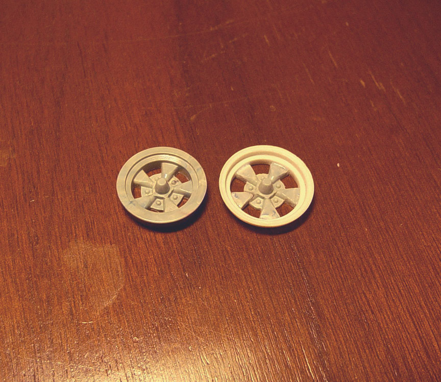 The Johan spokes were press fit into the American 5 spoke rim and you can really see the difference.
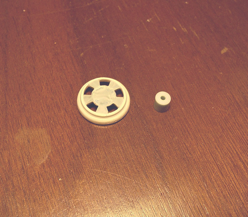 A hub from another mag wheel was cut off and will be added to the back of the mag.
The hub will be left a little longer to be more adaptable for other models.
 The rim wasn't seating to the tire as it was curved and wanted to keep popping out of the tire.
Files were used to make a new lip and bring the mag closer to the tire. 010"x .080 plastic strip was added to the outside to
make the mag look more presentable and fit better. The Inner Rim was also cut to have a wheel lip and the same plastic strip
was added around the outside of the Inner Rim.
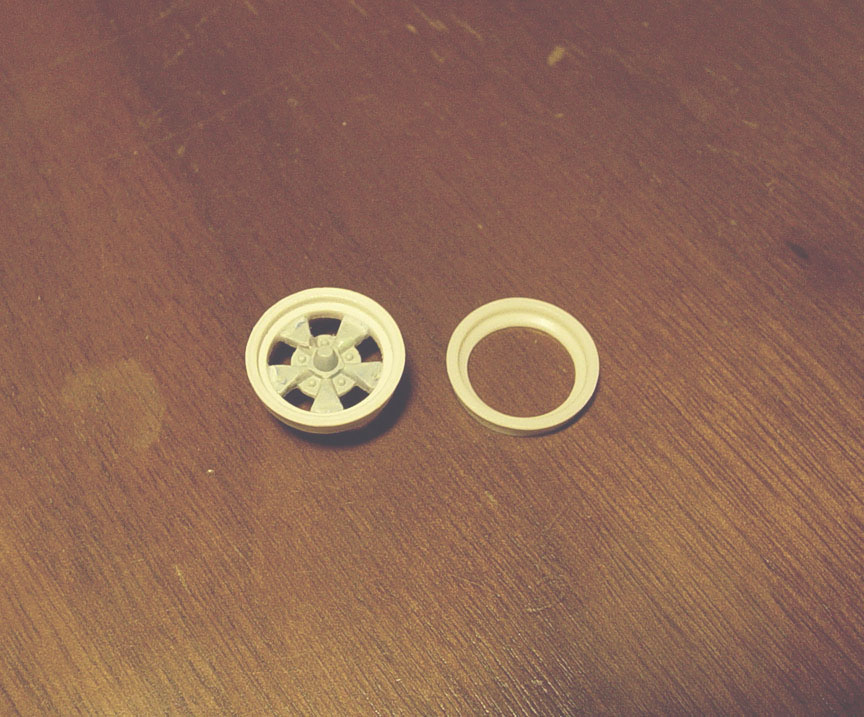 Master parts are finished !
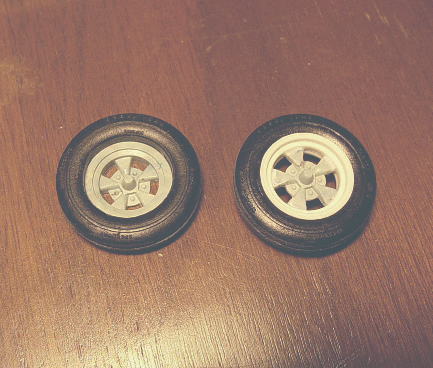 Although the Johan spokes are a multi-colored plastic, they will look really nice once in white resin.
You can see how the original Johan Lemans mag falls through a Speed City Goodyear Blue Streak Skinny Front Tire,
but our new 15" American Lemans Mag Wheel and Inner Rim will now fit all standard tires.
Master is finished !
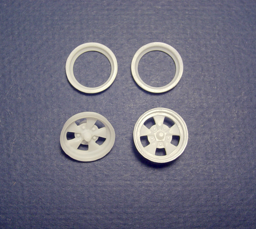
These American Lemans wheels are now available though Speed City only !